R
R
G
G
U
U
-
-
1
1
0
0
/
/
R
R
G
G
U
U
-
-
1
1
0
0
C
C
e
e
l
l
e
e
c
c
t
t
r
r
o
o
n
n
i
i
c
c
e
e
a
a
r
r
t
t
h
h
l
l
e
e
a
a
k
k
a
a
g
g
e
e
p
p
r
r
o
o
t
t
e
e
c
c
t
t
i
i
o
o
n
n
r
r
e
e
l
l
a
a
y
y
Page 9
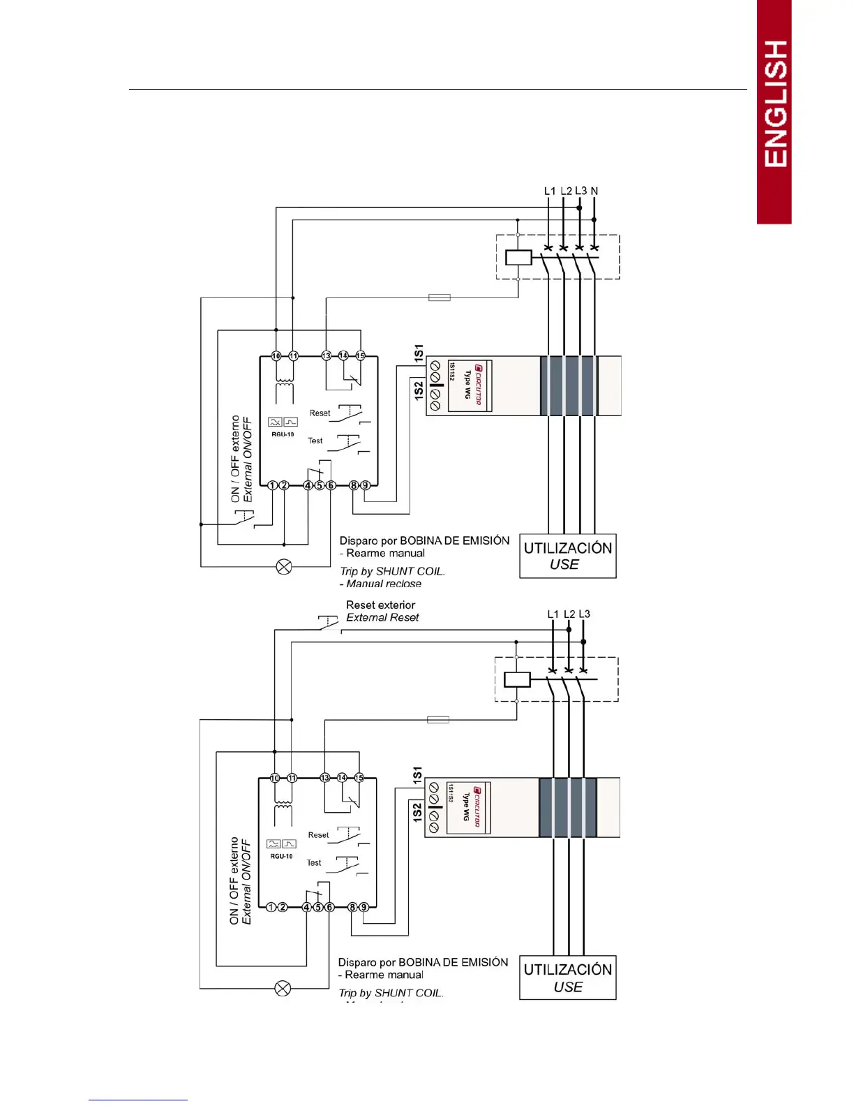
CONNECTION DIAGRAMS
RGU-10/RGU-10C connection with current emission coil. In the event of powering the equipment before the breaking
device (AUTOMATIC SWITCH) in an earth leakage trip situation because of a fault, test or toroid error:
1. Note the cause of the trip on the red display.
2. Reset the breaking device.
3. Press the RESET equipment.
Power supply from
24 to 230 V
ac
400 V
ac
power
supply
 Loading...