6
3. Adjust the instrument settings (TGC, output, etc.) to establish baseline
values for "normal" scanning. If the bottom of the phantom is seen,
adjust the gain settings until image goes entirely black. Record these settings
on the quality assurance record. These settings should be used for subsequent
testing.
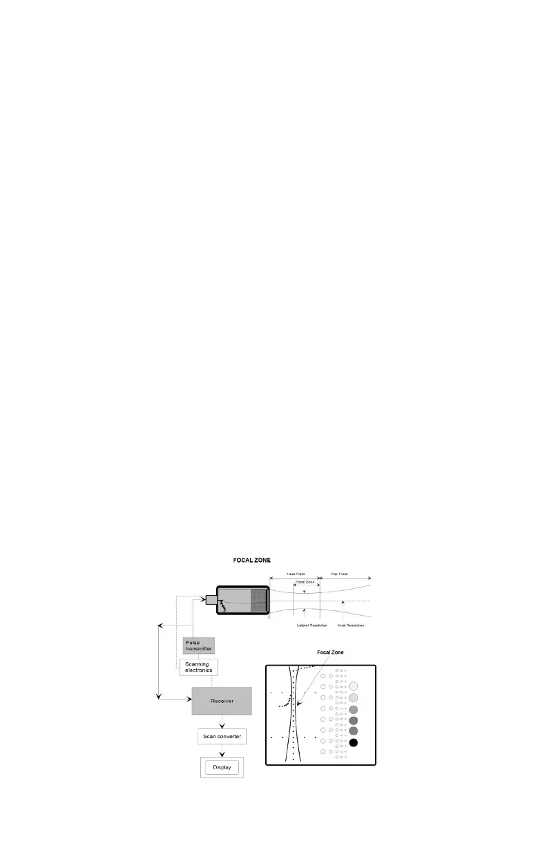
4. Position the transducer over the vertical group of line targets on the phantom,
until a clear image is obtained. Freeze the display and obtain a hard copy.
NOTE: A line rather than a dot is produced on the display. The length of the line is
indicative of the width of the beam. Therefore, targets inside the focal zone form a
shorter line than those outside of the focal zone. Adjustments in the gain settings
will change the length of the line targets displayed.
5. For a variable focused transducer, scans with several different focal zone
settings should be performed. Dynamically focused transducers may not
display changes in the width of the line targets. However a change in the
intensity can be observed upon adjustment of the transmitting focus of the
transducer.
6. Using the hard copy, draw a line connecting the ends of the echoes received
from the line targets (both sides), the line should form a smooth curve. This will
illustrate the shape of the sound beam. Now locate the narrowest portion,
this is the focal zone. Measure the width of the beam and the depth at this
point.
7. Document the depth of the focal zone and the measurement of the focal width
on the quality assurance record.
Results:
The location of the focal zone should agree with the manufacturer's specica-
tions and should not change with time. This applies to both xed and dynamically
focused systems. If changes occur corrective action should be considered.