13
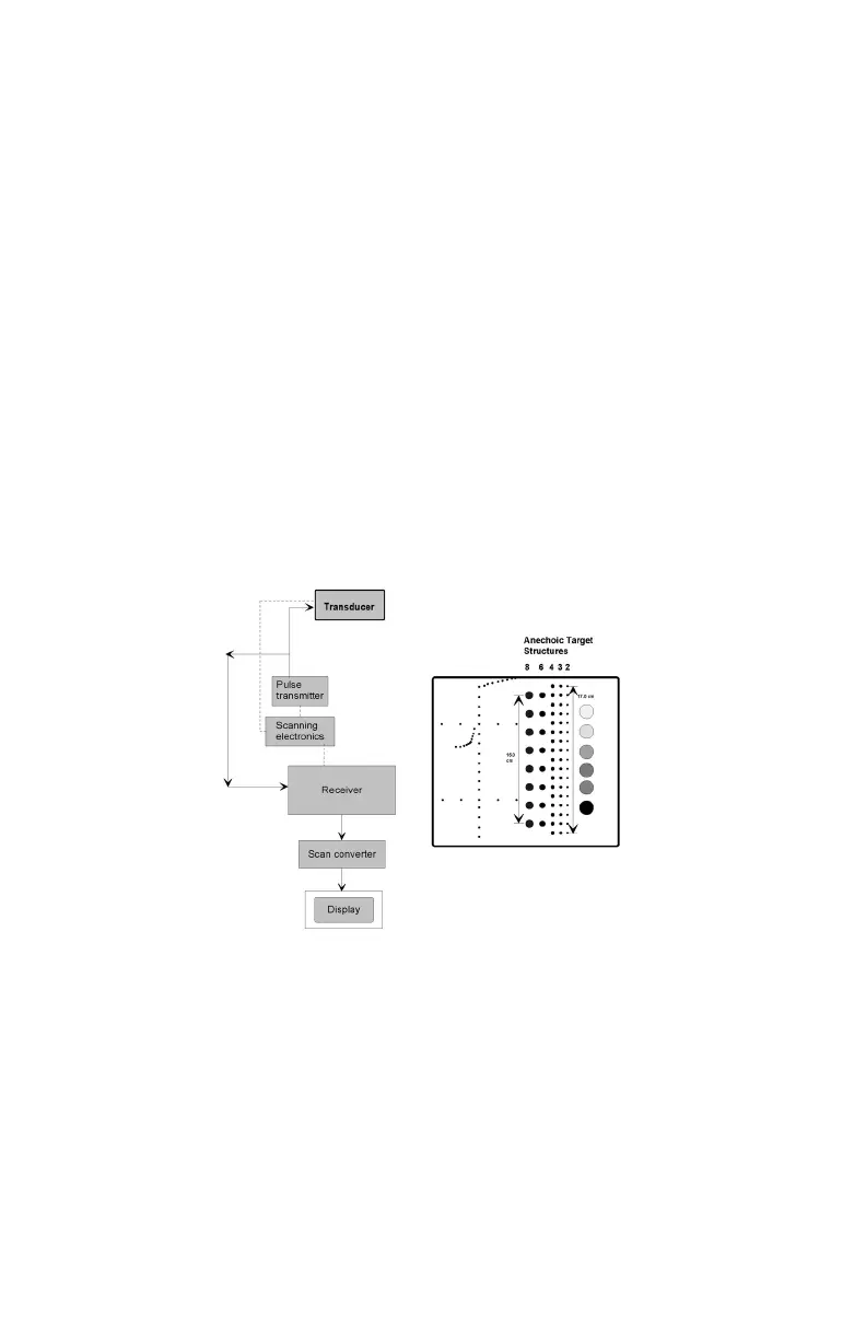
DEAD ZONE ASSESSMENT
The dead zone is the distance from the front face of the transducer to the rst
identiable echo at the phantom/patient interface. In the region of the dead zone no
clinical data can be collected. The dead zone occurs because an imaging sys-
tem cannot send and receive data at the same time. The depth of the dead zone
depends upon the frequency and performance of the transducer and the pulsing/
receiving section of the system.
The depth of the dead zone may be measured as follows:
1. Place the phantom on a clean, at surface with scanning surface #1
positioned for use.
5. Freeze the image and obtain a hard copy.
6. Examine the image to determine the rst and last target in each size group
displayed. Record the range of depths visualized for each group. Due to the
conguration of the sound beam small targets in the near eld may not be
imaged.
7. All ndings should be documented on the quality assurance record.
Results:
The targets should appear circular with sharp clearly dened edges, indicating an
abrupt transition from the echogenic to the anechoic region. The targets are an-
echoic and should be free of any internal echoes or ll-in. However, the presence of
internal system noise may manifest itself by producing an observable shade of gray
within the target area.
The specic values determined, while signicant in their own right, are somewhat
less important than stability over time. Performing this test on a routine basis at the
same instrument settings should produce the same results. Any changes should be
investigated.