5
Note: In addition to the above, this test should also be performed with output levels
set at the highest and lowest settings. This enables any changes in output to be
more easily detected.
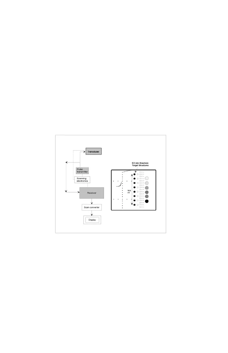
4. Position the transducer over the 8 mm group of anechoic targets.
5. Freeze image and obtain a hard copy.
6. Examine the image to determine the last or deepest target structure displayed.
Using the electronic calipers or the timing markers measure the depth of this
target.
7. Document the depth measurement on the quality assurance record.
Results:
The depth of penetration should not shift by more than 1.0 cm, when using this
phantom at same instrument settings and transducer. If a discrepancy occurs cor-
rective action should be considered by the individual Ultrasound Department.
BEAM PROFILE, FOCAL ZONE AND LATERAL RESPONSE WIDTH
The focal zone is the region surrounding the focal point in which the intensity and
the lateral resolution is the greatest. Clinically, structures examined within the focal
zone will provide the best diagnostic information obtainable. The focal zone can be
affected by changes in the pulsing/receiving section of the imaging system or dam-
age to the transducer. Testing is performed as follows:
1. Place the phantom on a clean, at surface with #1 scanning surface positioned
for use.
2. Apply an adequate amount of low viscosity gel or water to the scan surface. If
water is used, ll the scanning well slowly to avoid introduction of air bubbles.