EasyManua.ls Logo

Cisco 3000 Series - Page 80

Cisco 3000 Series
102 pages
Print Icon
To Next Page IconTo Next Page
To Previous Page IconTo Previous Page
Loading...
Ethernet
Cable
Assembly
Ethernet
Cable
Assembly
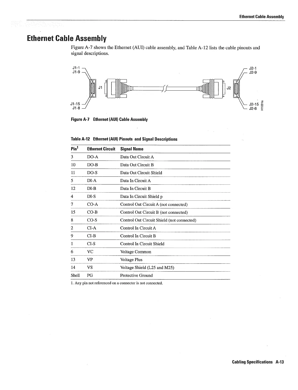
Figure
A-7
shows
the Ethernet
AUI
cable
assembly
and
Table
A-12
lists
the
cable
pinouts
and
signal descriptions
J1jJ2
J11
J2i5
Figure
A-i
Ethernet
AUI
Cable
Assembly
Table A-12
Ethernet
AUI
Pinouls
and
Signal
Descriptions
Pin1 Ethernet
Circuit
Signal
Name
DO-A
Data
Out
Circuit
10
DO-B
Data
Out
Circuit
11
DO-S
Data
Out
Circuit
Shield
DI-A
Data
In
Circuit
12
DI-B
Data
In Circuit
DI-S
Data
In Circuit
Shield
CO-A
Control
Out
Circuit
not
connected
15
CO-B
Control
Out
Circuit
not
connected
CO-S
Control
Out
Circuit
Shield
not
connected
Cl-A Control
In Circuit
Cl-B Control
In Circuit
Cl-S
Control
In Circuit
Shield
VC
Voltage
Common
13
VP
Voltage
Plus
14
VS
Voltage
Shield
L25
and
M25
Shell
PG
Protective
Ground
Any
pin
not
referenced
on
connector
is
not
connected
Cabling
Specifications
A-13