Do you have a question about the Cisco IE 3000 Series and is the answer not in the manual?
Target audience for the manual.
Document's scope and objectives.
Symbols and formatting used in the document.
List of related Cisco documentation.
How to get Cisco support and documentation.
General introduction to the Cisco IE 3000 switch and its purpose.
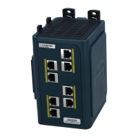
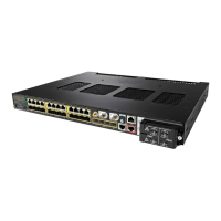
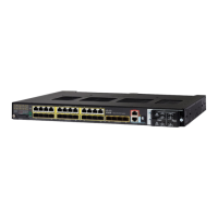
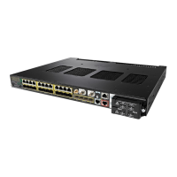
Details on switch models, front and rear panel descriptions.
Description of all switch ports, power, and console connectors.
Explanation of all front panel LEDs and their meanings.
Information on the power converter, compact flash, and management options.
Concepts for network setup and configuration.
Pre-installation checks, warnings, and guidelines.
Instructions for adding expansion modules and managing flash memory.
Procedures for POST, connecting console, and verifying switch.
How to install the switch and connect power/alarm circuits.
Guidance on connecting network cables to various ports.
Steps for connecting the optional power converter.
What to do after the switch is installed and powered.
General methods for diagnosing switch problems using LEDs and interfaces.
Checking POST results and verifying physical connections.
Resolving issues with cables, links, ports, and transceivers.
Troubleshooting spanning tree loops, speed, duplex, and autonegotiation.
Procedures for clearing configuration and recovering passwords.
How to find the switch's serial number for support.
Environmental operating temperature specifications for different locations.
Storage, humidity, shock, altitude, and power requirements.
Size and weight details of switches and modules.
Technical details for the optional power converter.
Standards applicable to hazardous location installations.
Pre-installation warnings, guidelines, and package verification for hazardous areas.
North American approval, EU EMC, and general installation guidelines.
Connecting modules, flash cards, power, alarms, and ports in hazardous areas.
Connecting the power converter and post-installation actions.
Overview of RJ-45, SFP, and console port connectors.
Cabling for 10/100, 1000BASE-T, and 100BASE-FX ports.
Specifications and requirements for SFP module connections.
Detailed pinout diagrams for cables and adapters.
Steps to connect to the switch CLI via console.
Guide to the initial setup program for configuring the switch.
Procedures for setting hostname, passwords, and IP addresses.
| Series | IE 3000 |
|---|---|
| Form Factor | Compact, ruggedized |
| Power Supply | 24 VDC |
| Mounting | DIN rail |
| Management | Web-based, CLI, SNMP |
| Network Protocols | IEEE 802.3 |
| MAC Address Table Size | 8000 |
| Input Voltage | 24 VDC |
| Power Consumption | Varies by model and configuration |
| Dimensions | Varies by model |
| Weight | Varies by model |
| MTBF | Varies by model |
| PoE | Available on select models (PoE and PoE+) |
| Category | Industrial Ethernet Switch |
