EasyManuals Logo

Cisco IE 3000 Series User Manual

Cisco IE 3000 Series
170 pages
To Next Page IconTo Next Page
To Previous Page IconTo Previous Page
Page #74 background imageLoading...
Page #74 background image
2-48
Cisco IE 3000 Switch Hardware Installation Guide
OL-13017-01
Chapter 2 Switch Installation
Connecting the Switch to the Power Converter
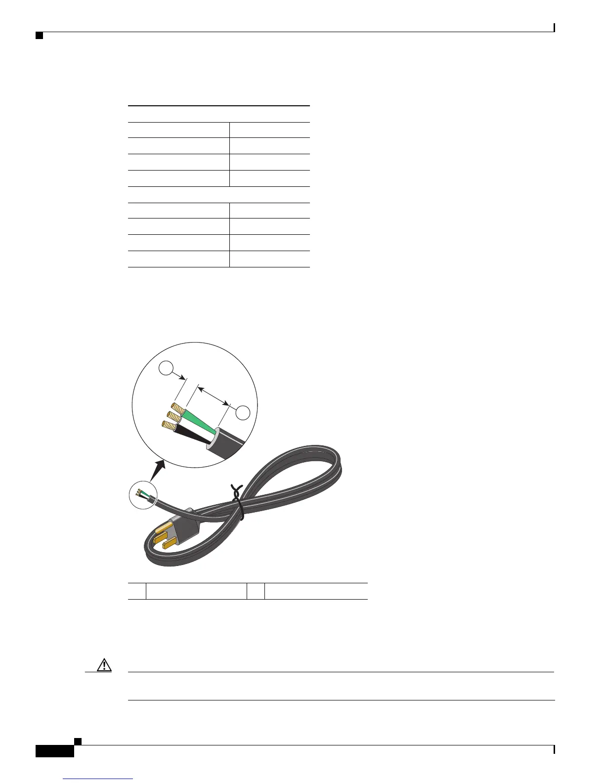
To prepare an AC power cord to connect to the power converter, strip the inner wire insulation to 0.25
inch (6.3 mm) ± 0.02 inch (0.5 mm). See
Figure 2-42.
Figure 2-42 Preparing the AC Power Cord
Connecting the AC Power Cord to the Power Converter
Follow these steps to connect the AC power cord to the power converter.
Caution AC power sources must be dedicated AC branch circuits. Each branch circuit must be protected by a
dedicated two-pole circuit breaker.
Ta b l e 2-2 AC-Power Cord-Color Codes
Europe (International)
Color Meaning
Brown Line
Blue Neutral
Green/yellow Earth ground
United States
Color Meaning
Black Line
White Neutral
Green Earth ground
1 0.25 inch (6.35 mm) 2 0.75 inch (19.05 mm)
280368
1
2

Table of Contents

Questions and Answers:

Question and Answer IconNeed help?

Do you have a question about the Cisco IE 3000 Series and is the answer not in the manual?

Cisco IE 3000 Series Specifications

General IconGeneral
SeriesIE 3000
Form FactorCompact, ruggedized
Power Supply24 VDC
MountingDIN rail
ManagementWeb-based, CLI, SNMP
Network ProtocolsIEEE 802.3
MAC Address Table Size8000
Input Voltage24 VDC
Power ConsumptionVaries by model and configuration
DimensionsVaries by model
WeightVaries by model
MTBFVaries by model
PoEAvailable on select models (PoE and PoE+)
CategoryIndustrial Ethernet Switch

Related product manuals