Statement 1091—Installation by an Instructed Person
Only an instructed person or skilled person should be allowed to install, replace, or service this equipment.
See statement 1089 for the definition of an instructed or skilled person.
Warning
Step 1 Save your configuration.
Step 2 Power down the chassis by moving the power switch to the OFF position. See Features, on page 1 for more information
about the power switch.
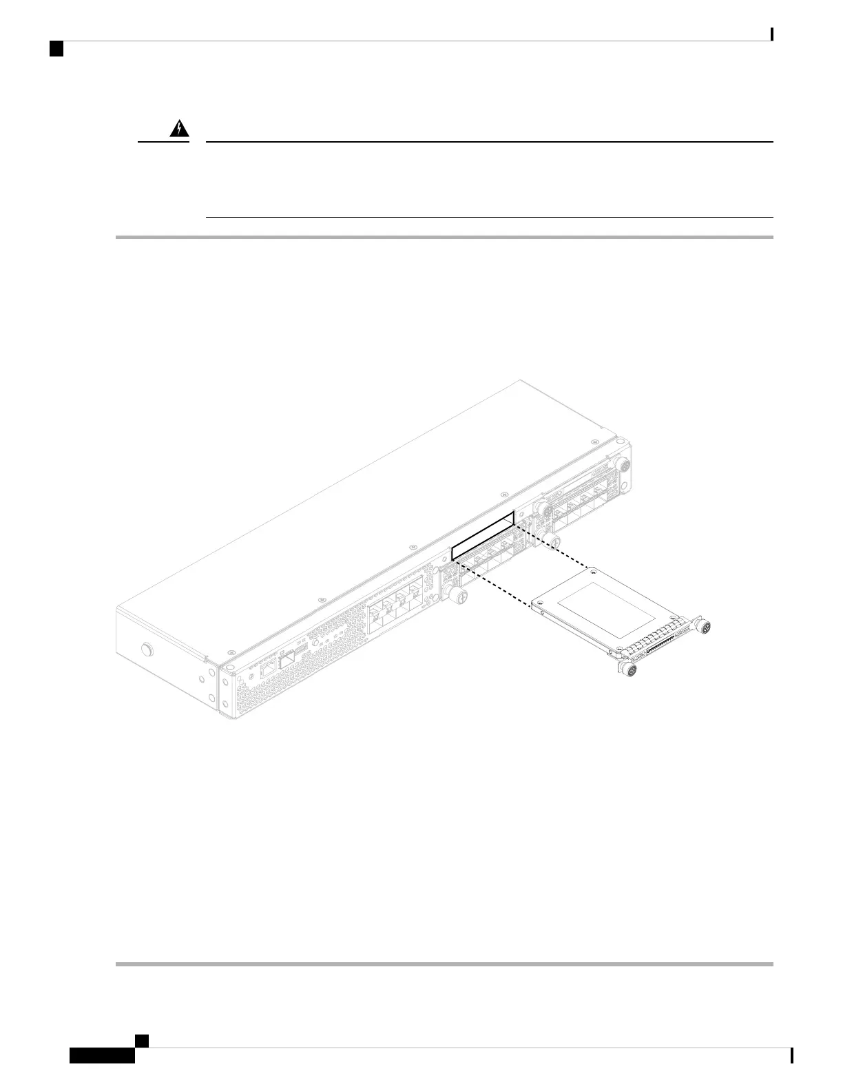
Step 3 To remove an SSD, face the front of the chassis, loosen the two captive screws on the SSD, and gently pull it out of slot
1 of the chassis.
Figure 43: Remove the SSD
Step 4 To replace the SSD, make sure the power switch is still in the OFF position, and then hold the SSD in front of slot 1 and
push it in gently until it is seated.
Step 5 To install the MSP SSD, make sure the power switch is still in the OFF position and then remove the blank faceplate in
slot 2 by loosening the captive screws on either side of the faceplate.
Step 6 Hold the MSP SSD in front of slot 2 and push it in gently until it is seated.
Do not switch the two SSDs. Only the optional MSP SSD can be installed in slot 2. If you remove it and
install it in slot 1, all stored file capture data is lost.
Caution
Step 7 Tighten the captive screws on either side of the SSD.
Step 8 Verify that the SSD is operational by checking the SSD LED. See Front Panel LEDs, on page 9 for a description of the
fan LEDs.
Cisco Firepower 4112, 4115, 4125, and 4145 Hardware Installation Guide
62
Installation, Maintenance, and Upgrade
Remove and Replace the SSD