3-5
Cisco ASA 5500 Series Getting Started Guide
78-19186-01
Chapter 3 Installing the ASA 5550
Installing the Chassis
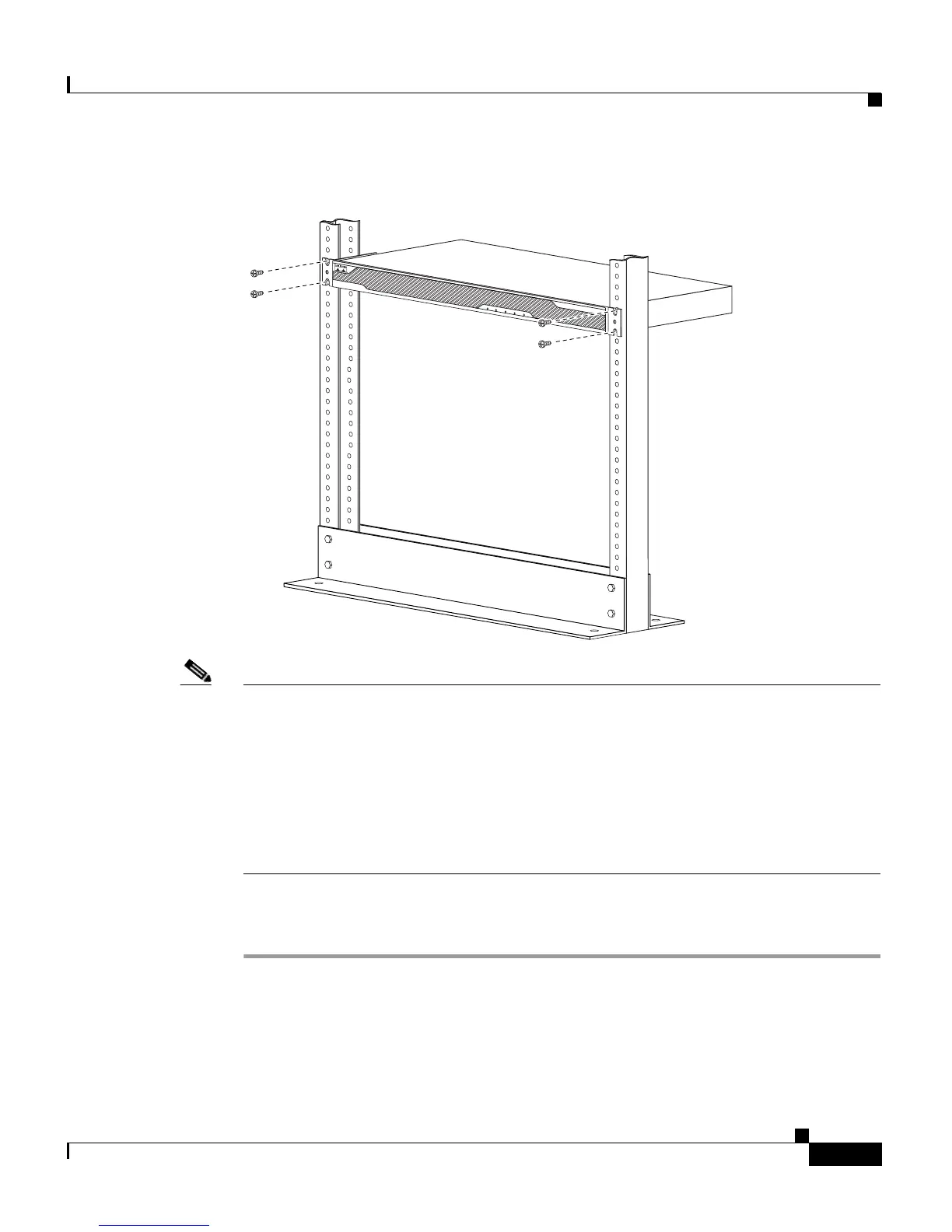
Figure 3-3 Rack-Mounting the Chassis
Note Figure 3-2 shows the rack mounting brackets attached to the rear of the chassis
while Figure 3-3 shows the rack mounting brackets attached to the front of the
chassis. You can attach the mounting brackets to the front or the rear of the chassis
so that you can have the front panel or the rear panel of the chassis facing outward.
Figure 3-2 shows the brackets attached to the rear so you can see how that
configuration appears while Figure 3-3 shows the brackets attached to the front so
that you can see how that configuration appears. In Step 1 and Step 2, you will
choose to have either the brackets rear mounted or front mounted but not both.
To remove the chassis from the rack, remove the screws that attach the chassis to
the rack, and then remove the chassis.
119633
POWER
STATUS
FLASH
ACTIVE
VPN
C
IS
C
O
A
S
A
5
5
4
0
SE
R
IE
S
A
da
ptiv
e S
ecurity
A
pp
lian
c
e

 Loading...