Chapter 5 Installing Optional SSMs
What to Do Next
5-10
Cisco ASA 5500 Series Getting Started Guide
78-19186-01
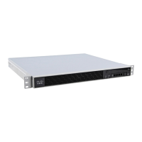
Figure 5-6 Removing the Screws from the Slot Cover
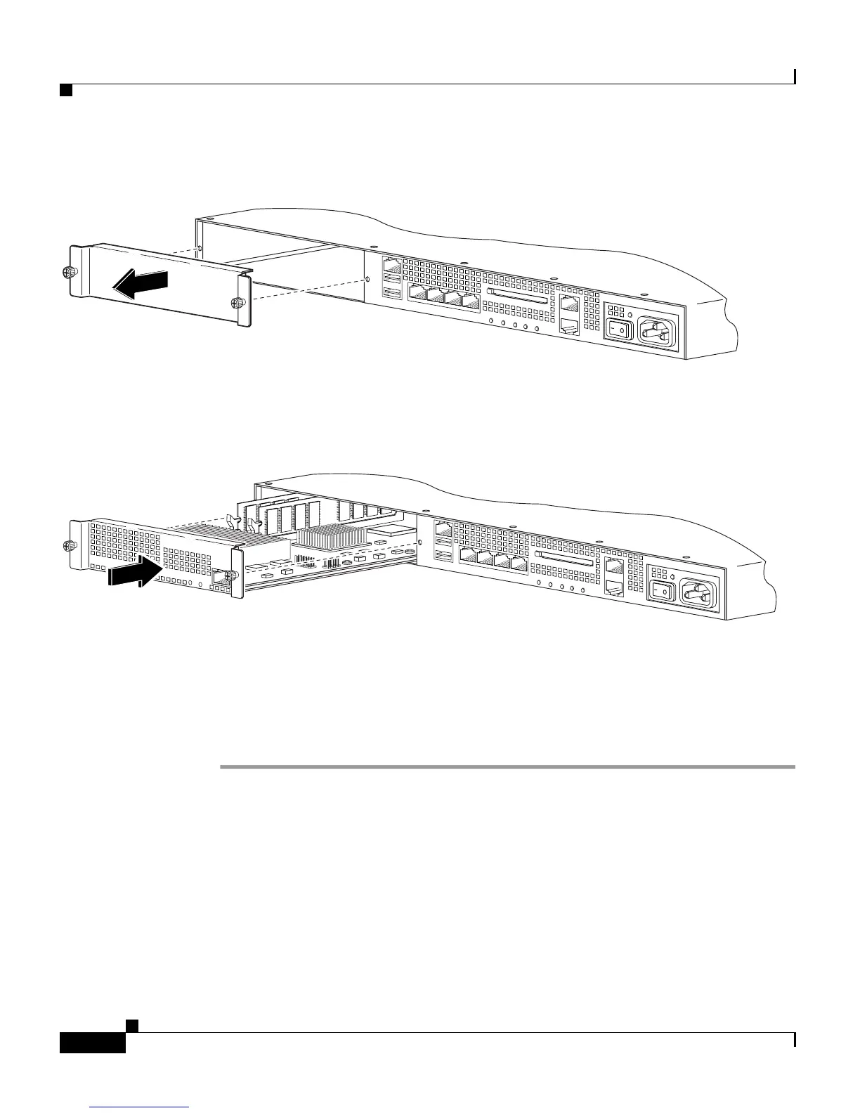
Step 4 Insert the SSM into the slot opening as shown in Figure 5-7.
Figure 5-7 Inserting the SSM into the Slot
Step 5 Attach the screws to secure the SSM to the chassis.
Step 6 Power on the adaptive security appliance. Check the LEDs. If the SSM is installed
properly, the POWER LED is solid green and the STATUS LED flashes green.
Step 7 Connect one end of the RJ-45 cable to the port and the other end of the cable to your
network devices.
What to Do Next
Continue with Chapter 6, “Connecting Interface Cables on the ASA 5500, ASA
5510, ASA 5520, and ASA 5540 Platforms.”
119642
LINK SPD
3
LINK SPD
2
LINK SPD
1
LINK SPD
0
MGMT
USB2
USB1
FLASH
POW
ER
STATUS
F
L
A
S
H
VPN
ACTI VE
119643
PW
R
STATUS
SPEED
LINK/ACT
LINK SPD
3
LINK SPD
2
LINK SPD
1
LINK SPD
0
MGMT
USB2
USB1
POWER
STATUS
FLASH
VPN
ACTIVE

 Loading...