Cisco 7000 and Cisco 7507 Air Filter and Chassis Blower Replacement Instructions 11
Replacing the Chassis Blower
Replacing the Chassis Blower
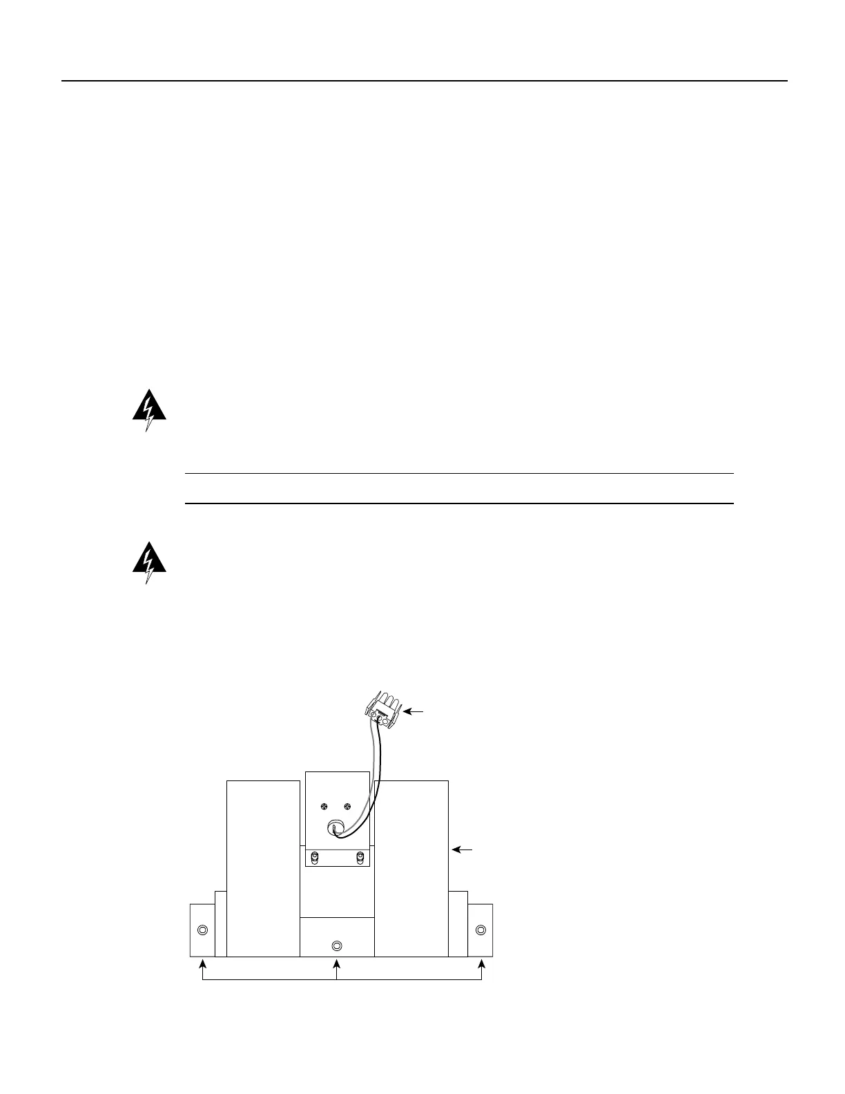
The blower is located at the bottom of the chassis interior. (See .) Two air ducts on the rear of the
blower, shown shaded in the illustration, fit snugly into the two cutouts in the backplane. The blower
is secured to the backplane with three large captive screws, which are shown in Figure 6. The captive
screws on most blowers are 3-mm center-hex Allen-head screws, but the earliest chassis shipped
used Phillips-head screws. A 3-mm T-handle driver with a long (9-inch) handle is shipped with the
spare blower.
Although the far left captive screw on the blower is slightly obscured from view by the left lip of the
chassis and the left blower air duct, an access hole in the lip of the chassis provides access to this
screw. By inserting the T-handle driver (or screwdriver) straight into the access hole, you should be
able to find the screw without any trouble. However, if you do have trouble finding the screw, and if
the lighting around the chassis is poor, you may need a flashlight to locate the screw and position the
driver correctly.
Warning Before working on a chassis or working near power supplies, unplug the power cord on
AC units; disconnect the power at the circuit breaker on DC units. (For translations of this safety
warning, refer to the section “Power Supply Disconnection Warning” on page 16.)
Note The following warning is for units equipped with a DC-input power supply.
Warning Before performing any of the following procedures, ensure that power is removed from
the DC circuit. To ensure that all power is OFF, locate the circuit breaker on the panel board that
services the DC circuit, switch the circuit breaker to the OFF position, and tape the switch handle of
the circuit breaker in the OFF position. (For translations of this safety warning, refer to the section
“DC Power Disconnection Warning” on page 17.)
Figure 6 Chassis Blower
Black (ground)
Purple (+24V)
Captive Allen-head screws
Blower power
connection
Blower
H1386a
 Loading...