EasyManuals Logo

Cisco 7000 Replacement Instructions

Cisco 7000
20 pages
To Next Page IconTo Next Page
To Previous Page IconTo Previous Page
Page #7 background imageLoading...
Page #7 background image
Cisco 7000 and Cisco 7507 Air Filter and Chassis Blower Replacement Instructions 7
Removing and Replacing the Front Chassis Panels
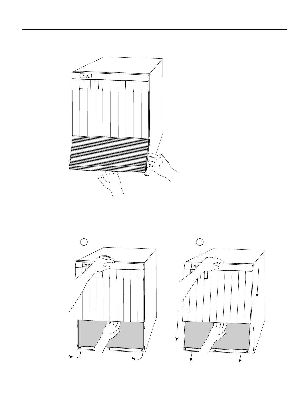
Figure 3 Removing the Bottom Front Panel
Step 4
Place one hand against the top front center of the panel to brace it. (See Figure 4a.) The top
of the panel acts as a pivot point when you pull the bottom out and away from the chassis.
Figure 4 Removing the Top Front Panel
UPPER
POWER
LOWER
POWER
NORMAL
Cisco 7000
H1335a
Cisco 7000
UPPER
POWER
LOWER
POWER
NORMAL
Cisco 7000
UPPER
POWER
LOWER
POWER
NORMAL
H1459a
a
b

Other manuals for Cisco 7000

Questions and Answers:

Question and Answer IconNeed help?

Do you have a question about the Cisco 7000 and is the answer not in the manual?

Cisco 7000 Specifications

General IconGeneral
Product TypeSwitch
Model7000
CategorySwitch
PortsVaries by configuration
Power SupplyRedundant power supplies supported
ManagementSNMP, CLI

Related product manuals