3-6
Cisco 7600 Series Router Supervisor Engine and Route Switch Processor Guide
OL-10100-04
Chapter 3 Installing and Configuring Route Switch Processors and Supervisor Engines
Installing a Supervisor Engine or Route Switch Processor
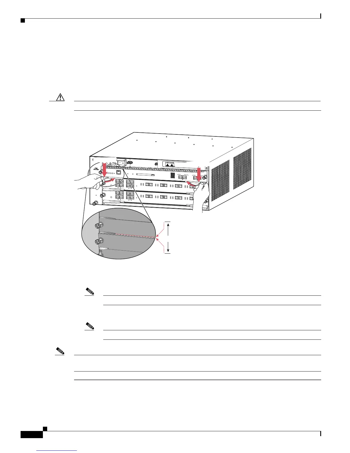
Step 5 Carefully slide the module into the slot until the EMI gasket on the module makes contact with the
module in the adjacent slot and both ejector levers have closed to approximately 45 degrees with respect
to the module faceplate. (See
Figure 3-3.)
Step 6 Using the thumb and forefinger of each hand, grasp the two ejector levers and press down to create a
small (0.040 inch [1 mm]) gap between the module EMI gasket and the adjacent module.
(See
Figure 3-3.)
Caution Do not press down too forcefully on the ejector levers. They will bend and be damaged.
Figure 3-3 Clearing the EMI Gasket
Step 7 While pressing down, simultaneously close both ejector levers to fully seat the module in the backplane
connector. The ejector levers are fully closed when they are flush with the module faceplate.
Note Failure to fully seat the module in the backplane connector can result in error messages.
Step 8 Tighten the two captive installation screws on the module.
Note Make sure the ejector levers are fully closed before tightening the captive installation screws.
Note Blank module filler plates (Cisco part number 800-00292-01) should be installed in any empty chassis
slots to keep dust out of the chassis and to maintain consistent airflow through the chassis.
63678
O
S
M
-
4
O
C
1
2
P
O
S
-
S
I
4
P
O
R
T
O
C
-
1
2
P
O
S
S
M
I
R
STATUS
1
1
2
2
3
3
4
4
RESET
LINK
LINK
LINK
LINK
CARRIER
ALARM
CARRIER
ALARM
CARRIER
ALARM
CARRIER
ALARM
ACTIVE
TX
R
X
TX
PORT 1
RX
ACTIVE
T
X
RX
TX
PO
RT 2
R
X
ACTIVE
TX
RX
TX
PORT 3
RX
ACTIVE
TX
RX
TX
PORT4
RX
O
S
M
-
4
O
C
1
2
P
O
S
-
S
I
4
P
O
R
T
O
C
-
1
2
P
O
S
S
M
I
R
STATUS
1
1
2
2
3
3
4
4
RESET
LINK
LINK
LINK
LINK
CARR
IER
ALARM
CARRIER
ALAR
M
CARRIER
ALARM
CARRIER
ALARM
ACTIVE
TX
RX
TX
PORT 1
RX
ACTIVE
TX
RX
TX
PORT 2
RX
AC
TIVE
T
X
RX
TX
PORT 3
R
X
ACTIVE
T
X
RX
TX
PORT4
RX
S
U
P
E
R
V
I
S
O
R
2
W
S
-
X
6
K
-
S
U
P
2
-
2
G
E
S
T
A
T
U
S
S
Y
S
T
E
M
C
O
N
S
O
L
E
P
W
R
M
G
M
T
R
E
S
E
T
CONSOLE
CONSOLE
PORT
MODE
PCMCIA
EJECT
PORT 1
PORT 2
Switch Load
100%
1%
L
I
N
K
L
IN
K
1mm
Gap between the module
EMI gasket and the
module above it.
Press down
Press down

 Loading...


