10
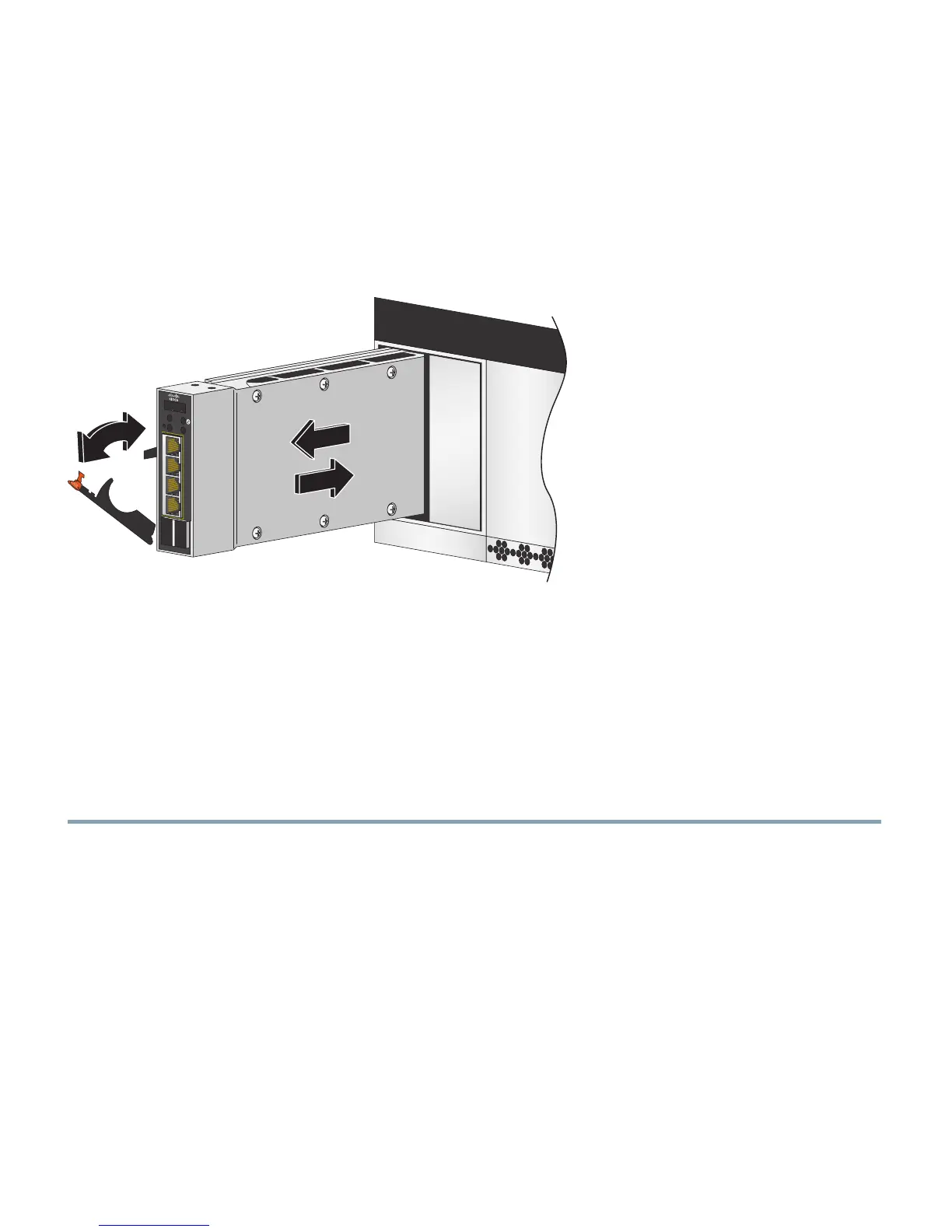
Step 6 Move the switch module release latch to the open position (perpendicular to the switch
module).
Step 7 Slide the switch module into the bay until it stops (Figure 5).
Figure 5 Installing the Switch Module
Step 8 Move the switch module release latch to the closed position. After you insert and lock the
switch module, it turns on, and the power-on self-test (POST) runs to verify that the switch
module is operating correctly.
The system power LED blinks green while POST is running, and then turns solid green when
POST is finished.
Step 9 Confirm that the system power LED is green. For a complete description of the switch module
LEDs, see the hardware installation guide on Cisco.com.
Step 10 Replace the acoustic-attenuation module, if applicable.