9
Follow these steps:
Step 1 Remove the acoustic attenuation module, if one is installed, from the rear of the blade
enclosure.
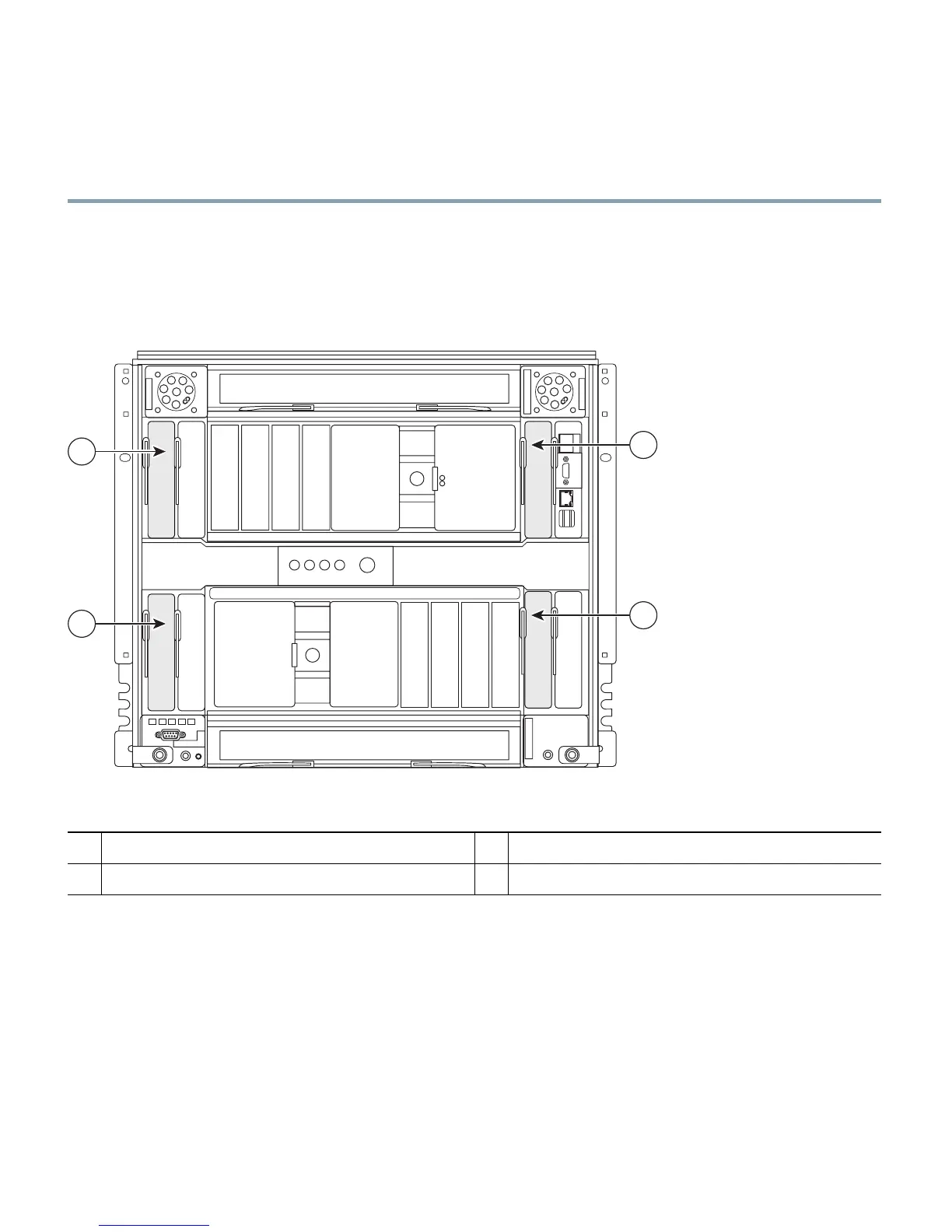
Step 2 Select the blade enclosure bay in which to install the switch module (Figure 4).
Figure 4 IBM BladeCenterH Rear-Panel View
Step 3 Remove the filler module from the selected bay. Store the filler module for future use.
Step 4 If you have not already done so, touch the static-protective package that contains the switch
module to any unpainted metal surface of the blade enclosure or any unpainted metal surface
on any other grounded rack component for at least 2 seconds.
Step 5 Remove the switch module from its static-protective package.
1
I/O module bay 1
3
I/O module bay 3
2
I/O module bay 2
4
I/O module bay 4
270428
1
3
4
2