EasyManuals Logo

Cisco Catalyst 3550 Getting Started Guide

Cisco Catalyst 3550
32 pages
To Next Page IconTo Next Page
To Previous Page IconTo Previous Page
Page #3 background imageLoading...
Page #3 background image
3
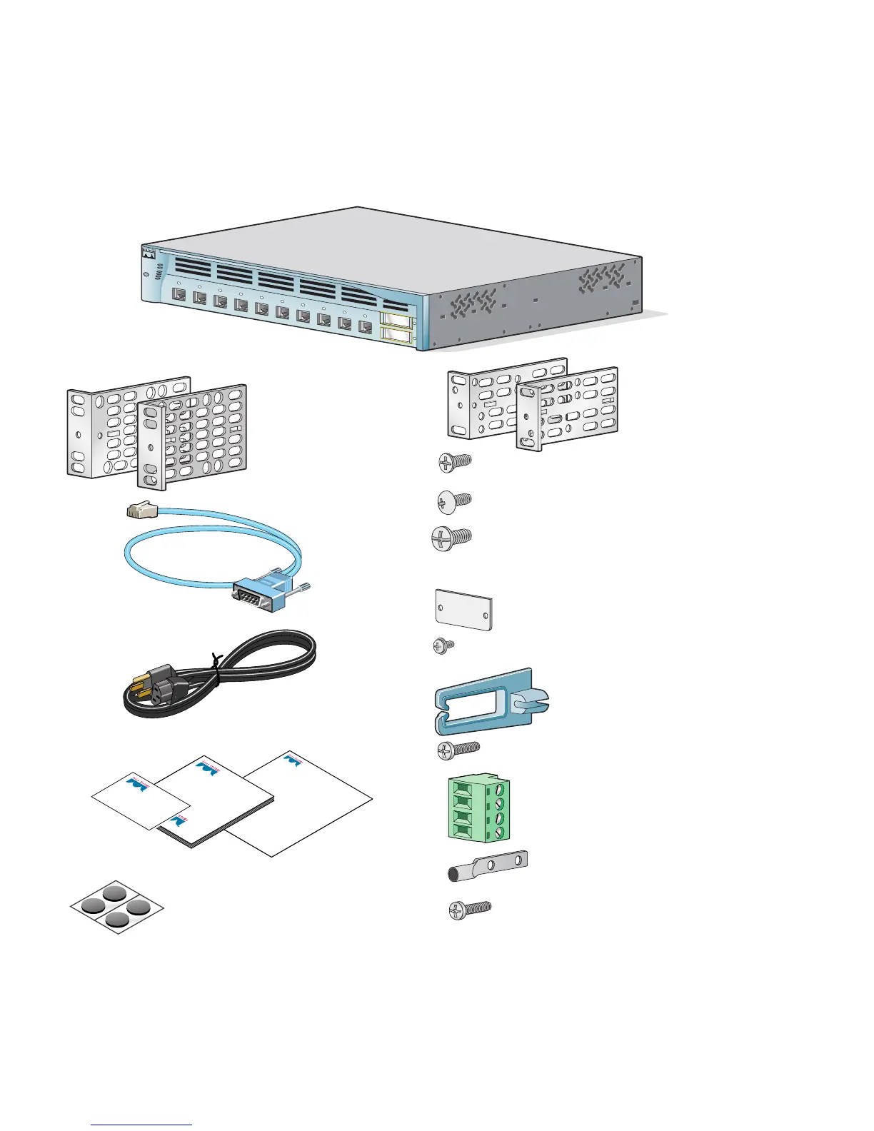
Shipping Box Contents
Regulatory Compliance
and Safety Information
for the
Catalyst 3550 Switch
Getting Started Guide
Cisco
Product Ownership
Registration card
Catalyst 3550 switch
Console cable
Two 19-inch
mounting brackets
Two 19-inch
mounting brackets
Four number-12 Phillips machine screws
Four number-8 Phillips truss-head screws
Six number-8 Phillips flat-head screws
Four rubber mounting feet
AC power cord (AC-powered switches only)
Connector cover for redundant
power system (RPS)
Two number-4 pan-head screws
Cable guide
One black Phillips machine screw
Documentation
Ground lug
(DC-powered switches only)
Two number-10-32 screws
Terminal block
(DC-powered switches only)
M
O
D
E
S
Y
S
T
E
M
R
P
S
S
T
A
T
U
S
U
T
IL
D
U
P
L
X
S
P
E
E
D
2
1
1
Catalyst 3550
2
3
4
5
6
7
8
9
10

Other manuals for Cisco Catalyst 3550

Questions and Answers:

Question and Answer IconNeed help?

Do you have a question about the Cisco Catalyst 3550 and is the answer not in the manual?

Cisco Catalyst 3550 Specifications

General IconGeneral
CategorySwitch
QoSYes
Form FactorRack-mountable
ManageableYes
RAM64 MB
ModelCatalyst 3550
Uplink Ports2 x GBIC (Gigabit Interface Converter) or SFP (Small Form-factor Pluggable)
Layer SupportLayer 3
VLAN SupportYes
MAC Address Table Size12000 entries
Routing ProtocolEIGRP
FeaturesQoS
Operating Temperature32 to 113°F (0 to 45°C)
Operating Humidity10 - 95% (non-condensing)
Ports24 or 48 10/100 ports

Related product manuals