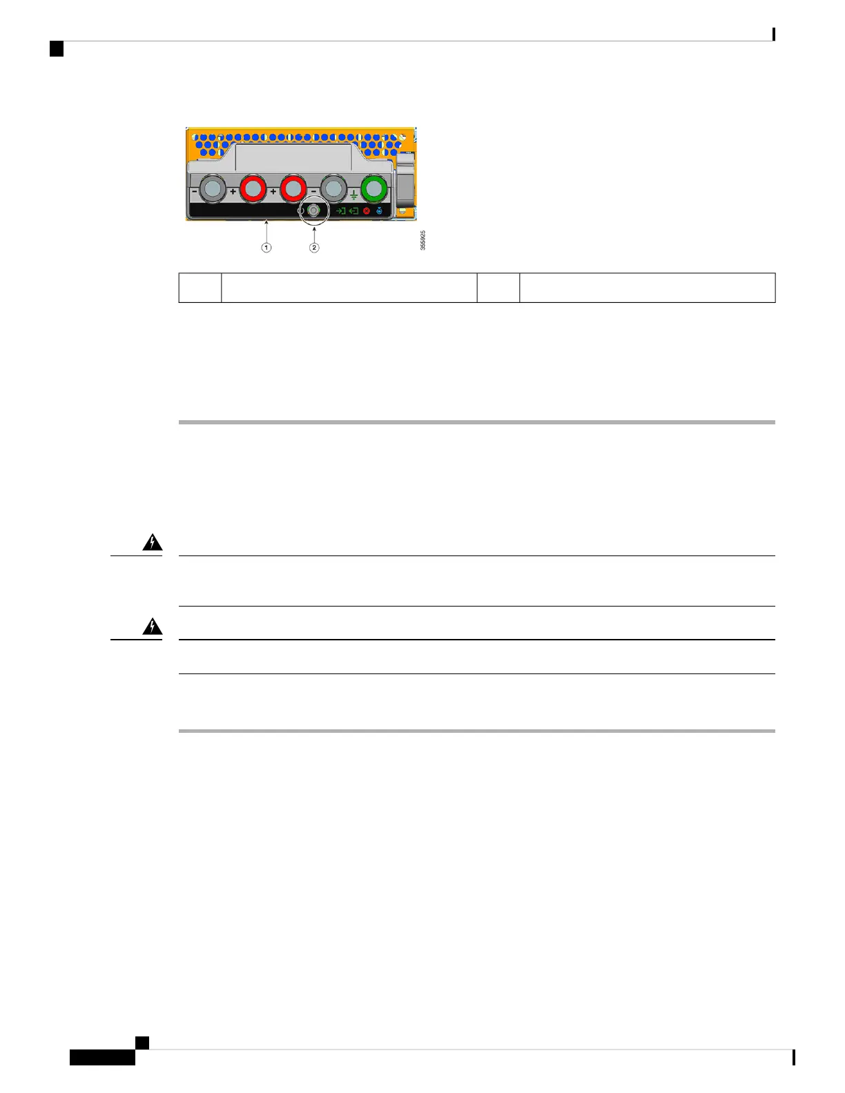
Power button2Front panel of the C9400-PWR-3200DC1
Step 2 Locate the circuit breaker on the panel board that services the DC circuit, and switch the circuit breaker to
the OFF position.
Step 3 Check that the INPUT LED on the power supply module is off.
The FAIL LED is illuminated for two to three seconds after DC input is disconnected through a circuit breaker.
Disconnecting the DC-Input Wires
To disconnect the DC-input wires, follow the steps described here.
Before you begin
Only trained and qualified personnel should be allowed to install, replace, or service this equipment. Statement
1030
Warning
No user-serviceable parts inside. Do not open. Statement 1073
Warning
Procedure
Step 1 Using a number one Phillips screwdriver, loosen the captive installation screw on the terminal block cover
and lift to open.
Cisco Catalyst 9400 Series Switches Hardware Installation Guide
112
Removing and Replacing FRUs
Disconnecting the DC-Input Wires