Step 4 Grasp the terminal block with one hand. Place your other hand underneath as you slide the power supply
module into the bay.
You will hear an audible click sound, which indicates that the module is locked into place, and connected
with the backplane. Only the terminal block housing is not flush with the chassis.
If you do not push the release latch in before you slide the module into the bay, you will not hear the click
sound, but this is an acceptable way of installing the module.
If the module is properly locked in place, you should not be able to remove the module without releasing the
latch.
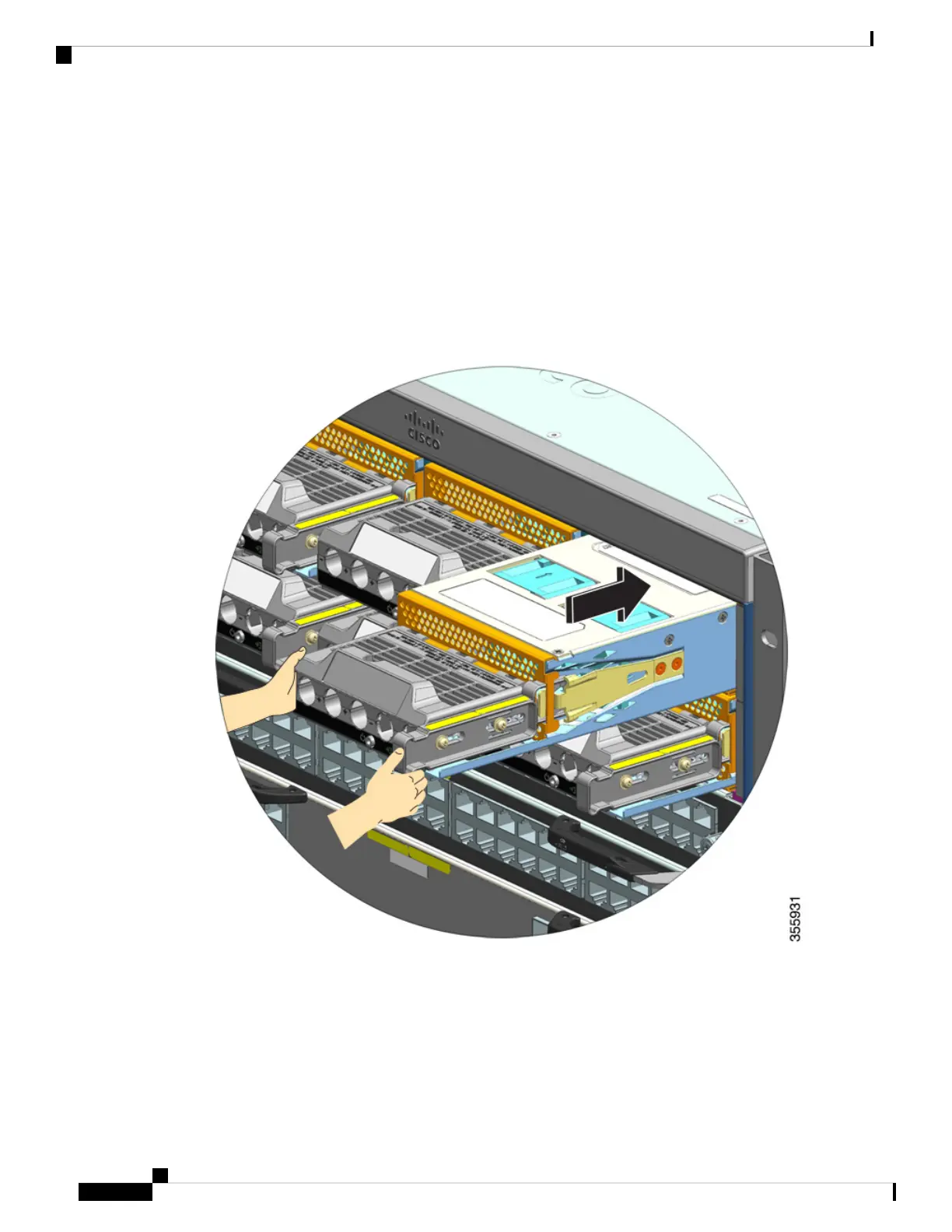
The following figure shows how a power supply module slides into the bay:
The following figure shows a power supply module that is fully installed in the bay:
Cisco Catalyst 9400 Series Switches Hardware Installation Guide
118
Removing and Replacing FRUs
Installing a DC-Input Power Supply Module in the Chassis