Step 3 Crimp the grounding wire in the barrel of the grounding lug. Verify that the ground wire is securely attached
to the ground lug.
Step 4 Secure the grounding lug to the system ground connector with two M4 screws. Ensure that the grounding lug
and the grounding wire do not interfere with other switch hardware or rack equipment.
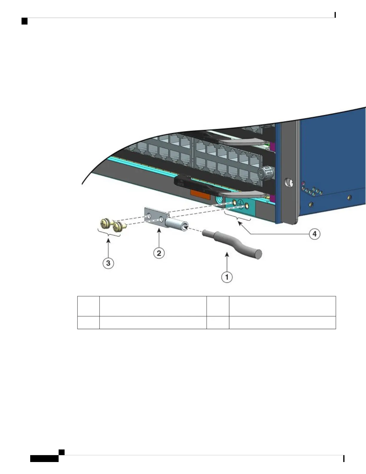
Figure 27: Locating and Connecting System Ground
M4 screws to secure the lug to the connector3Stripped end of the grounding wire inserted
into the open end of the grounding lug
1
System ground location4Grounding lug2
Cisco Catalyst 9400 Series Switches Hardware Installation Guide
80
Installing the Switch
Establishing System Ground