Chapter 1 Getting Started Guide
1-2
Getting Started Guide for the Catalyst Express 500 Switches
OL-9340-01
Quick Tour
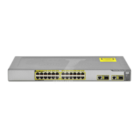
This illustration shows the Ethernet ports, LEDs, and other features on the switch.
To set up the switch, you use the SETUP button, an Ethernet port, and the
SYSTEM, SETUP, and port LEDs.
The model shown is a Catalyst Express 500-24LC. Your switch model might look
slightly different.
Catalyst Express 500
SERIES
2
1
1X
2X
P
OW
ER
O
V
E
R
ET
HE
RN
ET
11X
12X
4
3
6
5
8
7
10
9
12
11
14
13
13X
14X
23X
24X
16
15
18
17
20
19
22
21
24
23
25
25
26
26
SY
ST
EM
A
L
ER
T
P
oE
SE
TUP
SYSTEM
ALERT
PoE
SETUP
AC power connector
Security cable slot
side and rear panels
Power over Ethernet
(PoE) ports supply up to
15.4 W per port
Fast Ethernet ports
Dual-purpose uplink ports:
SFP module and
10/100/1000BASE-T
SETUP button
Port LEDs
Autonegotiate and auto-MDIX
enabled on all ports
Switch LEDs:
SYSTEM - switch status
ALERT - events detected
PoE - PoE status
SETUP - setup mode