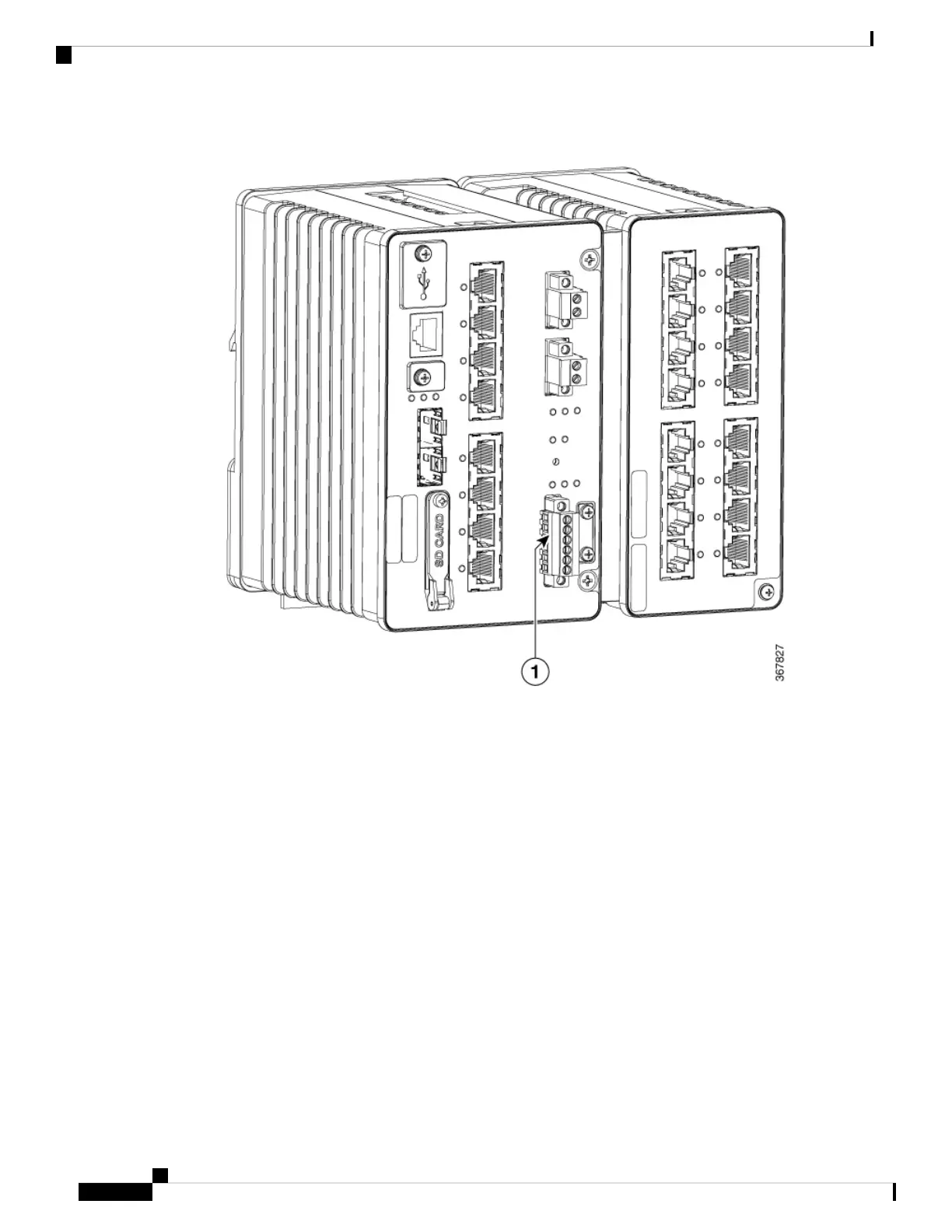
Figure 8: Alarm Connector
2. Measure two strands of twisted-pair wire (16-to-18 AWG) long enough to connect to the external alarm
device. Choose between setting up an external alarm input or output circuit.
3. Use a wire stripper to remove the casing from both ends of each wire to 0.25 inch (6.3 mm) ± 0.02 inch
(0.5 mm). Do not strip more than 0.27 inch (6.8 mm) of insulation from the wires. Stripping more than
the recommended amount of wire can leave exposed wire from the alarm connector after installation.
4. Insert the exposed wires for the external alarm device into the connections based on an alarm input or
output circuit setup. For example, to wire an alarm input circuit, complete the IN1 and REF connections.
5. Use a ratcheting torque flathead screwdriver to tighten the alarm connector captive screw (above the
installed wire leads) to 2 in-lb (0.23 N-m).
Switch Installation
22
Switch Installation
Wiring the External Alarms

 Loading...