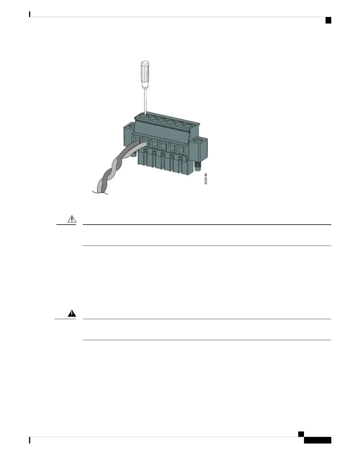
Figure 9: Securing the Alarm Connector Captive Screws
Figure 10: Securing the Alarm Connector Captive Screws
Do not over-torque the power and alarm connectors’ captive screws. The torque should not exceed 2in-lb
(0.23N-m).
Caution
6. Repeat Step 2 through Step 5 to insert the input and output wires of one additional external alarm device
into the alarm connector.
The first alarm device circuit is wired as an alarm input circuit; the IN1 and REF connections complete the
circuit. The second alarm device circuit is wired as an alarm output circuit that works on a normally open
contact basis; the NO and COM connections complete the circuit.
Attaching the Alarm Connector to the Switch
Failure to securely tighten the captive screws can result in an electrical arc if the connector is accidentally
removed. Statement 397
Warning
To attach the alarm connector to the front panel of the switch, follow these steps:
1. Insert the alarm connector into the receptacle on the switch front panel.
2. Use a ratcheting torque flathead screwdriver to tighten the captive screws on the sides of the alarm
connector.
Switch Installation
23
Switch Installation
Attaching the Alarm Connector to the Switch

 Loading...