30
Installing and Connecting the Router
Power-Supply Modules
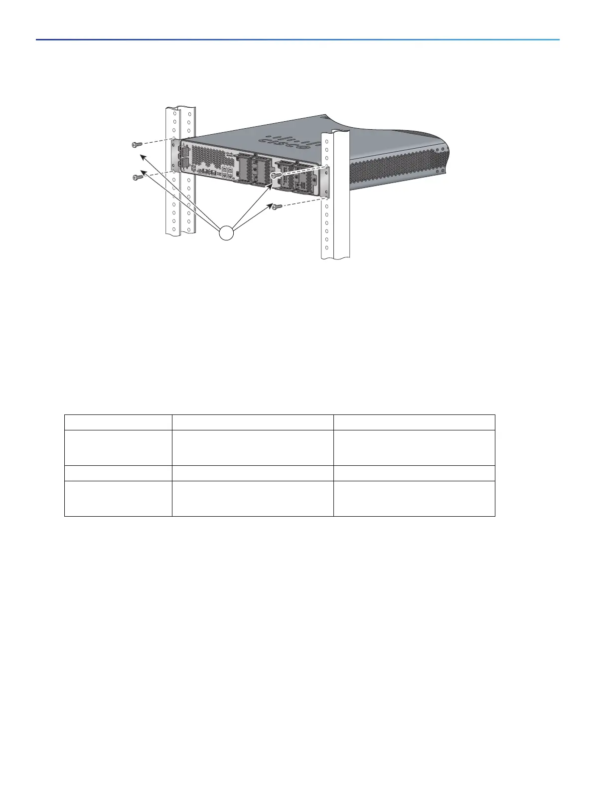
Figure 4 Mounting the Chassis in a Rack (Typical Installation)
Power-Supply Modules
This section describes how to connect AC power and DC power to the Cisco CGR 2010 router. This section also
describes how to protect the Cisco CGR 2010 router terminal block from exposure with the terminal block cover and shut
off power.
Table 1 on page 30 summarizes the three power-supply modules available for the Cisco CGR 2010 router.
See Figure 5 on page 31.
1 Mounting screws (4)
SFP 0/0
SFP 0/1
GE 0/0
GE 0/1
CONSOLE
AUX
EN
EN
Cisco CGR 2010
PSU2PSU1
L
N
N
L
+
Lo
-
-
Lo
+
-
HI
+
+
HI
-
0
1
EN
SPD
CF
1
PS
2
ACT
SYS 0
1
SL
SL
SLOT 3 SLOT 2
SLOT 1 SLOT 0
277448
CONN CONN
0-3
4-7
CD/LP AL CD/LP AL
P1 P0
1
Table 1 Power-Supply Modules
Model Description Voltage Range
PWR-RGD-AC-DC High-voltage AC or DC. 100-240VAC
100-250VDC
PWR-RGD-LOW-DC Low-voltage DC. 24-60VDC 10 amps
PWR-RGD-AC-DC-C High-voltage AC or DC.
China-specific model.
100-240VAC
100-250VDC