Command-line interface user manual
_________________________________________________________________________________________________
__________________________________________________________________________
© 2021 Cisco and/or its affiliates. All rights reserved Page 27 of 37
• The first line shows the access point (AP) to which the device
being interrogated is currently connected AP.
• The second and third lines show other available APs and the
status of those APs.
• The information in the time 1 cell shows that a time of 1ms was
taken to create the new MPLS tunnel.
• The information in the acq 0 cell shows a connection acquisition
time of 0ms. In other words, the vehicle radio took 0ms to connect
to the wireless infrastructure radio from outside the coverage zone.
• The information in the handoff cell shows a timestamp at which the
handoff occurred of 1486754405.001680979.
• The information in the updated cell shows the timestamp at which
the last control packet was received from the connected AP.
WLAN Rx:
The tables above show the physical status of the wireless TX
(transmission) connection and RX (reception) connection:
• rate shows the data transfer rate in Mbps.
• SNR shows the signal-to-noise ratio.
• RSSI shows the received signal strength in decibel-milliwatts.
• LER shows the link error rate.
• PER shows the packet error rate.
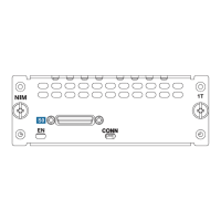
The table above shows the role of the radio unit’s Ethernet ports:
• If a Down result is shown, the port is not connected.
• If a mesh result is shown, the port allows only MPLS packets.
• If an ingress/egress mesh result is shown, the port allows all types
of data packets.