E-11
Cisco Physical Security Multiservices Platform Series User Guide
OL-21838-03
Appendix E 16 x D1 and 8 x D1 Video Capture Cards
Connecting the Video Capture Card to the BNC Breakout Panel
Step 2 Rack-mount the BNC breakout panel behind the server.
Figure E-8 shows the panel and connections.
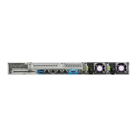
Figure E-8 BNC Breakout Panel
Step 3 Attach a CIVS-CAB-16V multi-channel video cable from each video capture card to the BNC breakout
panel.
Note • The same multi-channel video cable is used for 8 or 16 channel cards.
• Video capture channels are defined by the location of the card in the server, not the numbers labeled
on the BNC panel. See the
“Understanding Video Channel Numbers” section on page E-6 for more
information.
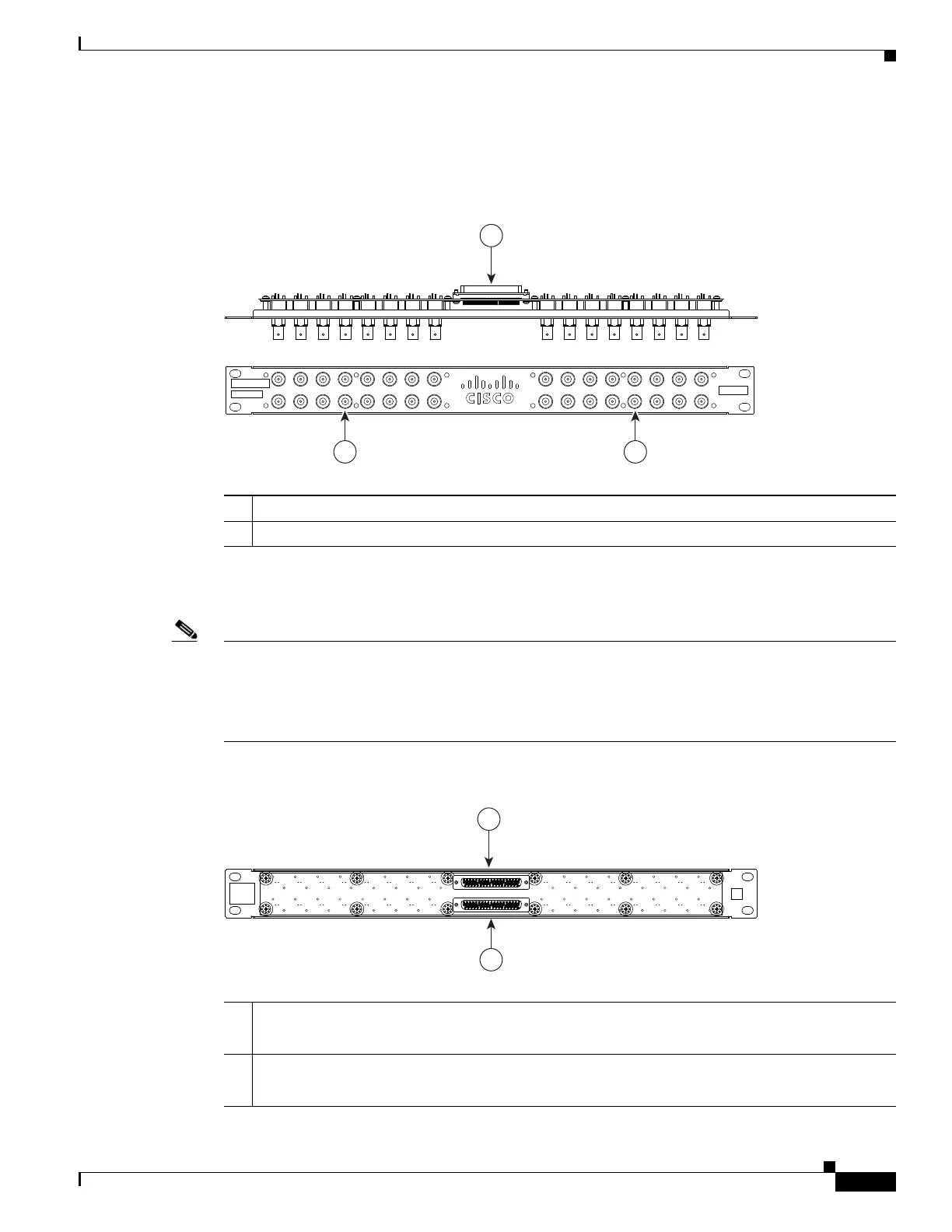
Figure E-9 DB37 Receptacles on Rear of BNC Breakout Panel
1 Two DB37 receptacles for the multi-channel video cables that connect to the video capture cards
2 BNC connectors for the video camera coaxial cables
278117
1
2 2
12345678
17 18 19 20 21 22 23 24
9 10111213141516
25 26 27 28 29 30 31 32
1 Multi-channel video cable connector for video ports labeled 1 through 16.
Note 8 channel cards use ports 1 through 8.
2 Multi-channel video cable connector for video ports labeled 17 through 32.
Note 8 channel cards use ports 17 through 24.
278118
1
2
 Loading...