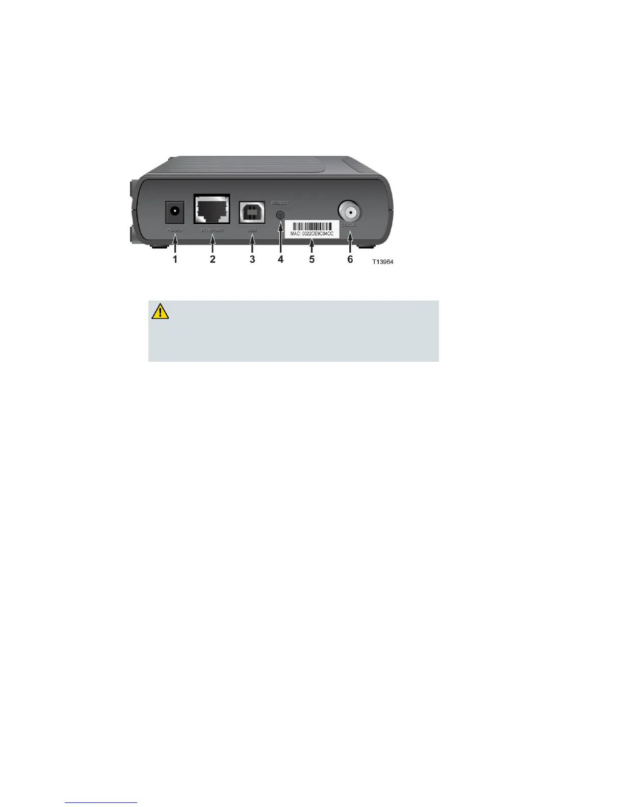
Back Panel Description
The following illustration describes the back panel components of the DPC3000 and
EPC3000 DOCSIS 3.0 cable modems.
1 POWER—Connects the cable modem to the 12 VDC output of the AC
power adapter that is provided with your cable modem
2 ETHERNET—Bridged RJ-45 1000/100BASE-T Ethernet port connects to
the Ethernet port on your PC
3 USB—USB 2.0 port connects to the USB port on your PC
Note: The USB port may not be included on all modems.
4 REBOOT—Reset-to-Default momentary switch (Factory Reset)
Note: This button is for maintenance purposes only. Do not use unless
told to do so by your service provider.
5 MAC Address Label—Displays the MAC address of the cable modem
6 CABLE—F-Connector connects to an active cable signal from your
service provider