EasyManua.ls Logo

Cisco DPC3000 - LED Status Indicators; Understanding Indicator Functions

Cisco DPC3000
38 pages
Print Icon
To Next Page IconTo Next Page
To Previous Page IconTo Previous Page
Loading...
32 4023034 Rev D
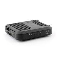
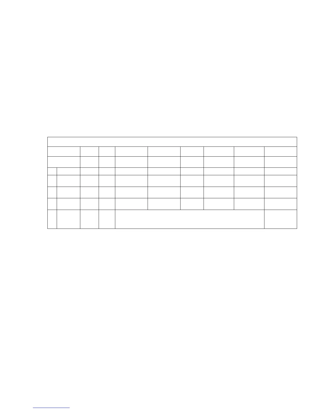
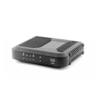
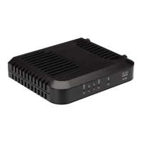
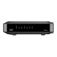
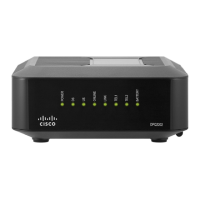
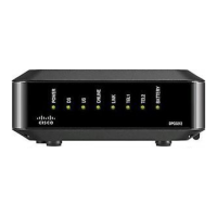
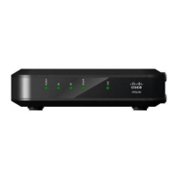
Front Panel LED Status Indicator Functions
Initial Power Up, Calibration, and Registration
The following chart illustrates the sequence of steps and the corresponding
appearance of the cable modem front panel LED status indicators during power-up,
calibration, and registration on the network. Use this chart to troubleshoot the power
up, calibration, and registration process of your cable modem.
Note: After the cable modem completes step 8 (Registration Complete), the modem
proceeds immediately to step 9, Normal Operations. See the table in Normal
Operations (on page 33).
Front Panel LED Status Indicators During Initial Power-Up, Calibration, and Registration
Step
1
2
3
4
5
6
7
8
Front Panel
Indicator
Power
Up
Self
Test
Downstream
Scan
Downstream
Signal Lock
Ranging
Requesting
IP Address
Registering
Registration
Complete
1
POWER
On
On
On
On
On
On
On
On
2
DS
Blinks
On
1 sec
Blinks
On
On
On
On
On
3
US
Blinks
On
1 sec
Off
Off
Blinks
On
On
On
4
ONLINE
Blinks
On
1 sec
Off
Off
Off
Off
Blinks
On
5
LINK
Off
On
1 sec
Off - When no devices are connected to the Ethernet or USB ports
On - When devices are connected to the Ethernet or USB ports
Blinks - When data activity is present
On

Related product manuals