10
Cisco ENCS 5400-W Series Quick Start Guide
Powering Up and Initializing the ENCS 5400-W Device
Powering Up the ENCS 5400-W Device
To power up the ENCS 5400-W device, follow these steps.
Step 1 Attach the power cord to the power supply unit in the ENCS 5400-W device and then attach the other
end of the power cord to the grounded power outlet.
Step 2 Wait for approximately three minutes.
Step 3 Verify the power status of the system by looking at the system power status LED. The power status LED
blinks in amber color during initial boot up and in solid amber when the system reaches the standby
power mode.
3
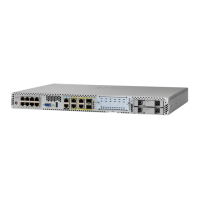
VGA connector • Connects a monitor to the device. It supports a display
resolution of up to 1600 x 1200 16bpp @ 60Hz.
4
USB 3.0 port • To connect to a mouse, keyboard, or any other USB
device. Using a USB hub, you can connect more than one
USB device to this port.
Because this port is backward compatible, you can also
use an older version of USB devices on this port.
5
Serial console port for CPU • Provides a connection to initially configure the main
system's CPU, including the NFVIS software that runs
there, using a traditional serial terminal. The terminal
should be configured for 9600 8-N-1.
6
Ethernet management port for
CPU
• Connects to the CPU in your device.
7
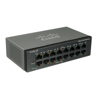
Front panel Gigabit Ethernet
ports
• A set of two dual ports.
For each RJ45 port, there is a corresponding fiber optic
port. At a given time, you can use either the RJ45
connection or the corresponding fiber optic port.
8
LEDs for front panel Gigabit
Ethernet ports
• There are four LEDs for the front panel: the first two
LEDs are for the first set of ports and the last two LEDs
are for the second set of ports.
If both RJ45 and fiber optic ports are enabled when the
system boots, the fiber optic port is used and the RJ45 port
is disabled.
9
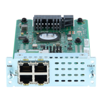
Network Interface Module
(NIM) expansion slot
• NIM is not used on ENCS 5400-W models (it is used on
ENCS 5400 models).
10
Drive Bay 0 • Drive bay 0
11
Drive Bay 1 • Drive bay 1
12
Ethernet management port for
CIMC
• CIMC is the component in the device that monitors the
health of the entire system.
13
Serial console port for CIMC • Provides a connection to initially configure the main
system's CPU, including the NFVIS software that runs
there, using a traditional serial terminal. The terminal
should be configured for 9600 8-N-1.
# Component Description
 Loading...