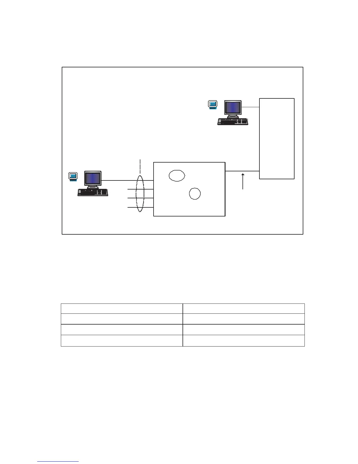
accessed through the management-module VLAN. Review the following figure
only as an example of establishing a TCP/IP session through the management
module or through the external interface.
eth1
Mgmt VLAN
VLAN 1
Default VLAN
VLAN 2
MGT1
15
17
18
19
20
Telnet
MM
eth0
HTTP
192.168.70.1
eth1
192.168.70.125
192.168.70.126
192.168.70.127
10.10.1.1
10.10.1.2
Client A
Client B
GbE
Client A manages the Gigabit Ethernet switch module through the default
management-module configuration interface. The management module is
always enabled and always a member of VLAN 1. VLAN 1 can never be
disabled. You can always manage the Gigabit Ethernet switch module over this
interface, provided that the IP addresses of the client, the management module,
and the Gigabit Ethernet switch module are on the same subnet, as shown in
the following table.
Network entity IP address
Client A 192.168.70.1
Management module 192.168.70.125
Gigabit Ethernet switch module 192.168.70.127
Chapter 3. Configuring the Gigabit Ethernet switch module 21