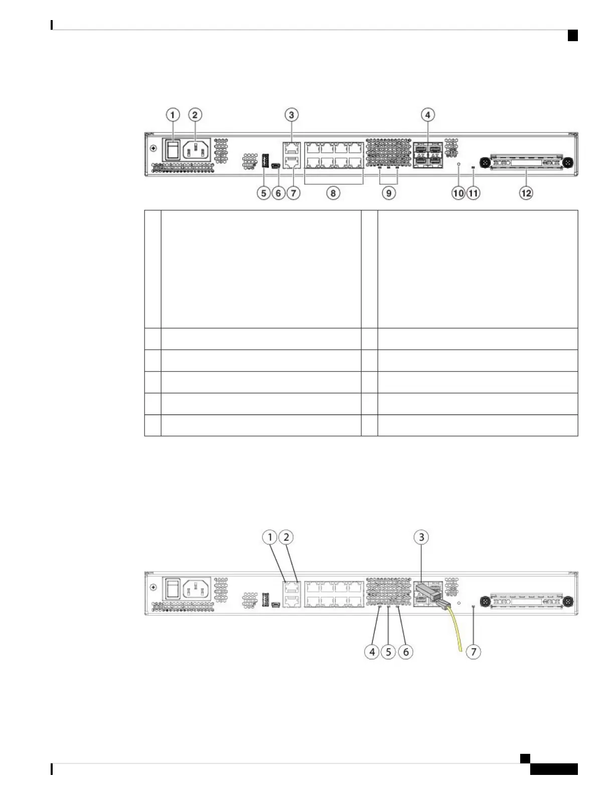
Figure 7: Firepower 1100 Series Rear Panel
Power cord socket2Power switch
The power switch provides a way to
gracefully shut down the system and
place it in standby. The power supply
and fan remain active and the fan may
continue to spin at slow speed. To
achieve total power shut down, unplug
the power supply from the chassis.
Note
1
SFP ports (numbered 9 through 12)4Management port3
USB Mini B console port6USB Type A port5
Network data ports8RJ-45 (8P8C) console port7
Reset button10Status LEDs9
SSD bay12SSD LED11
Rear Panel LEDs
The following figure shows the LEDs on the rear panel of the Firepower 1100 series and describes their states.
Figure 8: Firepower 1100 Series Rear Panel LEDs
Cisco Firepower 1100 Series Hardware Installation Guide
9
Overview
Rear Panel LEDs

 Loading...


