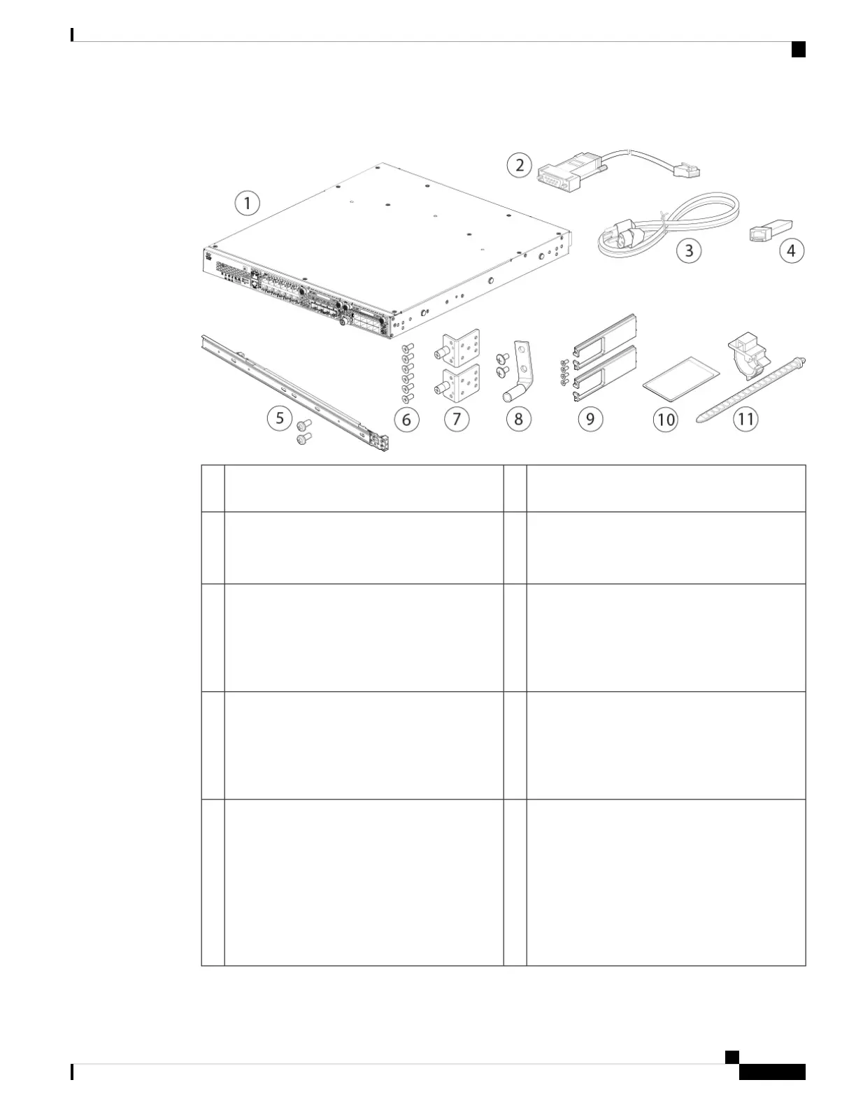
Figure 4: Firepower 2130 and 2140 Package Contents
Console cable RJ-45 to DB-9 (part number
72-3383-01)
2Firepower 2130 or 2140 chassis1
SFP transceiver
(Optional; in package if ordered)
4One or two power cords (country-specific)
See Power Cord Specifications, on page 37 for
a list of supported power cords.
3
Six 8-32 x 0.25-inch slide rail locking bracket
Phillips screws (part number 48-101429-01)
6Slide rail kit (part number 800-103711-01)
• Left and right slide rails
• Two M3 x 0.5 x 6-mm Phillips screws (part
number 48-101144-01)
5
One ground lug kit (part number 69-100359-01)
• One #6 AWG, 90 degree, #10 post ground
lug (part number 32-0608-01)
• Two 10-32 x 0.38-inch Phillips screws
8Two slide rail locking brackets (part number
700-105350-01)
7
Cisco Firepower 2100
This document has a URL pointing to the
hardware installation guide, a URL pointing the
regulatory and safety guide, and a QR code and
URL pointing to the Getting Started Guide.
10Cable management bracket kit (part number
69-100376-01)
• Two cable management brackets (part
number 700-106377-01)
• Four 8-32 x 0.375-inch Phillips screws (part
number 48-2696-01)
(Optional; in package if ordered)
9
Cisco Firepower 2100 Series Hardware Installation Guide
7
Overview
Package Contents

 Loading...


