PSU-1
• Off—The power supply module is not
present or not detected.
• Green—The power supply module is present
and working properly.
• Amber—The power supply module is
present but a fault or problem has been
detected.
10Fiber Port
• Green—Port is enabled, the link partner is
detected.
• Amber—Port is enabled, but the link partner
is not detected.
• Green, flashing—Port is enabled; network
activity is detected.
9
FAN
• Off—The environmental subsystem is not
active yet.
• Green—The fans are running normally. It
may take up to one minute for the LED
status to turn green after power is on.
• Amber—One fan has failed. The system can
continue to operate normally, but fan service
is required.
• Amber, flashing—Two or more fans have
failed, or the fan tray has been removed from
the system. Immediate attention is required.
12PSU-2
• Off—The power supply module is not
present or not detected.
• Green—The power supply module is present
and working properly.
• Amber—The power supply module is
present but a fault or problem has been
detected.
11
SSD2 Alert Status
• Off—SSD has normal activity.
• Amber—SSD failure.
14SSD1 Alert Status
• Off—SSD has normal activity.
• Amber—SSD failure.
13
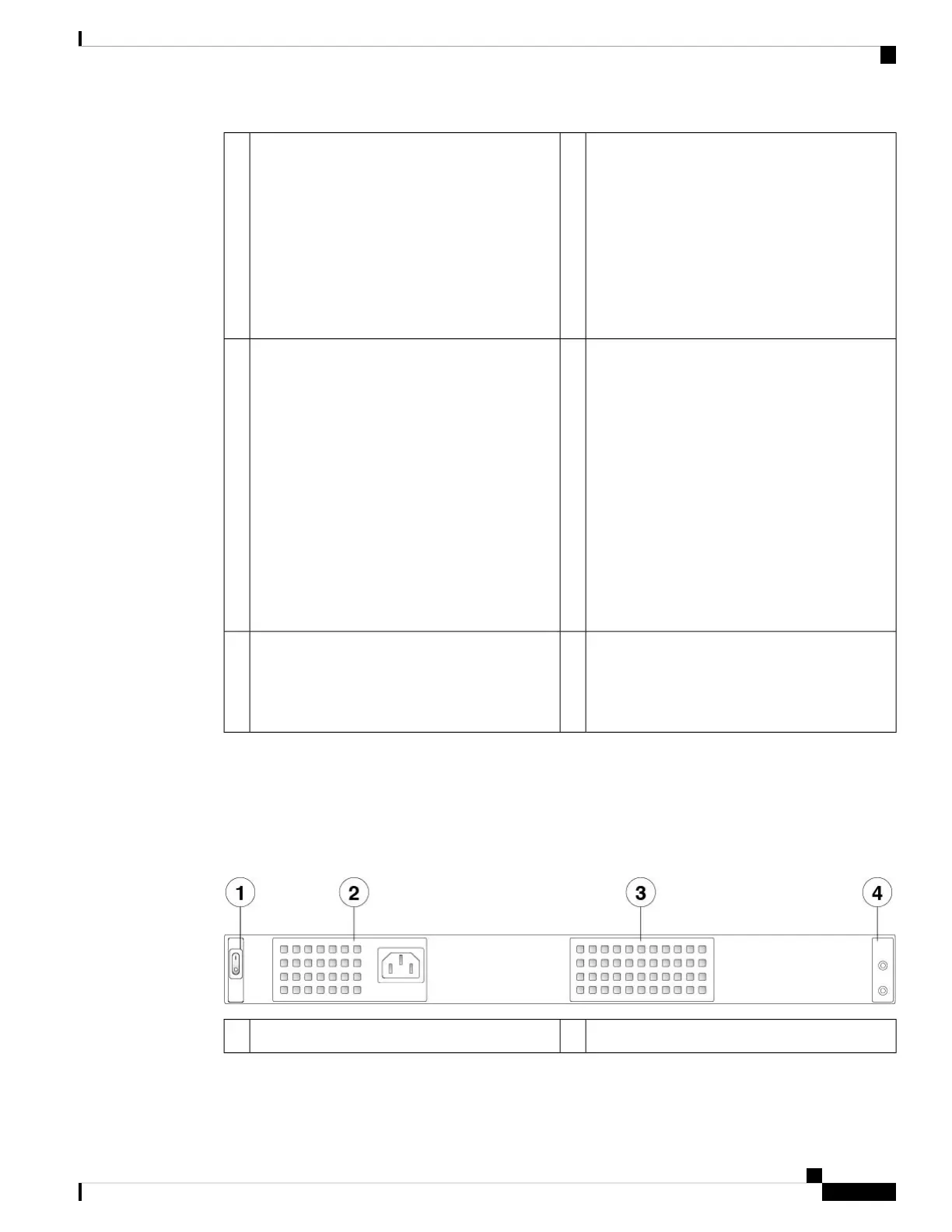
Rear Panel
The following figure shows the rear panel of the Firepower 2110 and 2120.
Figure 13: Firepower 2110 and 2120 Rear Panel
Fixed power supply module2Power on/off switch1
Cisco Firepower 2100 Series Hardware Installation Guide
17
Overview
Rear Panel

 Loading...


