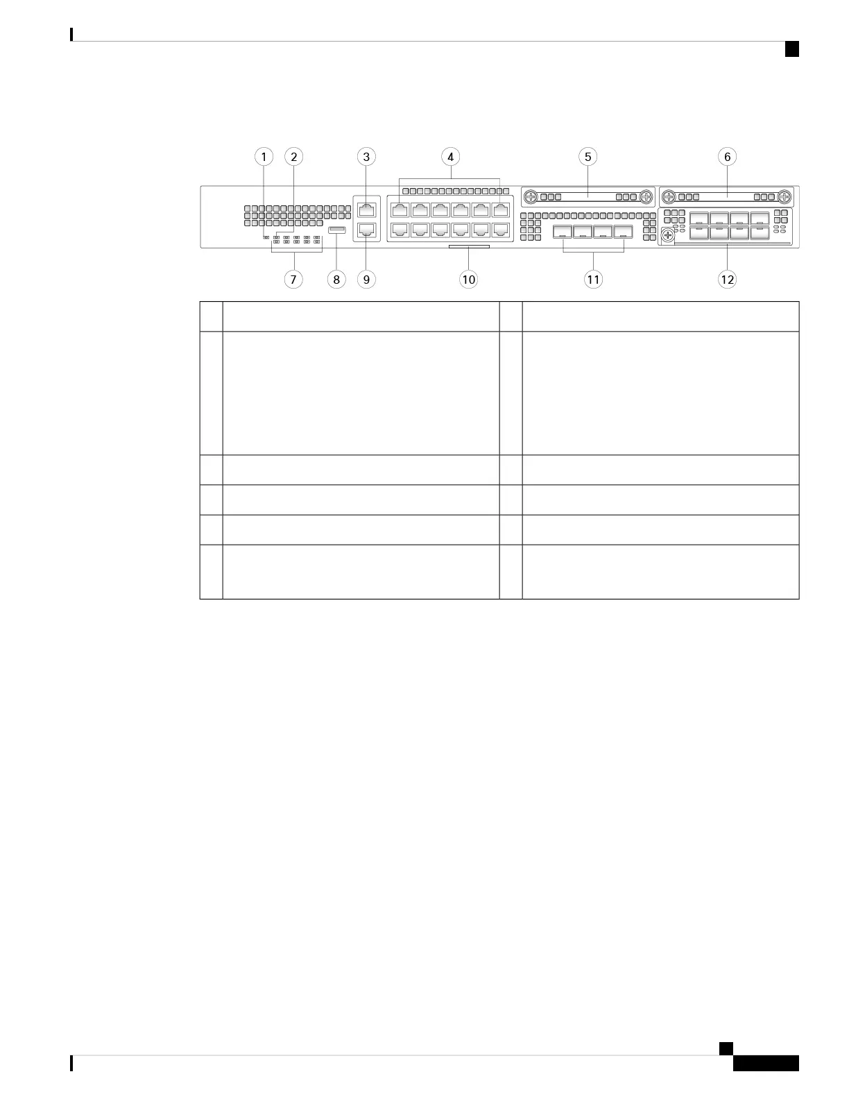
Figure 10: Firepower 2130 and 2140 Front Panel
Locator LED2Power LED1
12 RJ-45 1 G/100 M/10 M auto duplex/auto
MDI-X Base-T ports
Ethernet 1/1 through 1/12 labeled top to bottom,
left to right
4Gigabit Ethernet management port:
• Firepower Threat Defense—Management 0
(also referred to as Management 1/1 and
Diagnostic 1/1)
• ASA—Management 1/1
3
SSD 26SSD 15
Type A USB 2.0 port8System LEDs7
Pullout asset card with chassis serial number10RJ-45 console port9
Network module (network module slot 1)12Four fixed SFP+ (1 Gb/10 Gb) ports
Fiber ports 1/13 through 1/16 labeled left to right
11
Management Port
The Firepower 2100 chassis has an RJ-45 copper management port.
RJ-45 Console Port
The Firepower 2100 chassis has a standard RJ-45 console port. You can use the CLI to configure your
2100 through the RJ-45 serial console port by using a terminal server or a terminal emulation program
on a computer.
The RJ-45 (8P8C) port supports RS-232 signaling to an internal UART controller. The console port does
not have any hardware flow control, and does not support a remote dial-in modem. The baud rate is 9600.
You can use the standard cable found in your accessory kit to convert the RJ-45 to DB-9 if necessary.
Type A USB Port
You can use the external Type A USB port to attach a data-storage device. The external USB drive
identifier is usbA:. The Type A USB port supports the following:
• Hot swapping
• USB drive formatted with FAT32
• Boot kickstart image from ROMMON for discovery recovery purposes
• Copy files to and from workspace:/ and volatile:/ within local-mgmt. The most relevant files are:
Cisco Firepower 2100 Series Hardware Installation Guide
11
Overview
Front Panel
 Loading...


