When you toggle the power switch from ON to OFF, it takes several seconds for the system to power down.
Do not remove the power cable until the power LED is off. After removing power from the chassis either by
moving the power switch to OFF or unplugging the power cord, wait at least 10 seconds before turning power
back ON.
Note
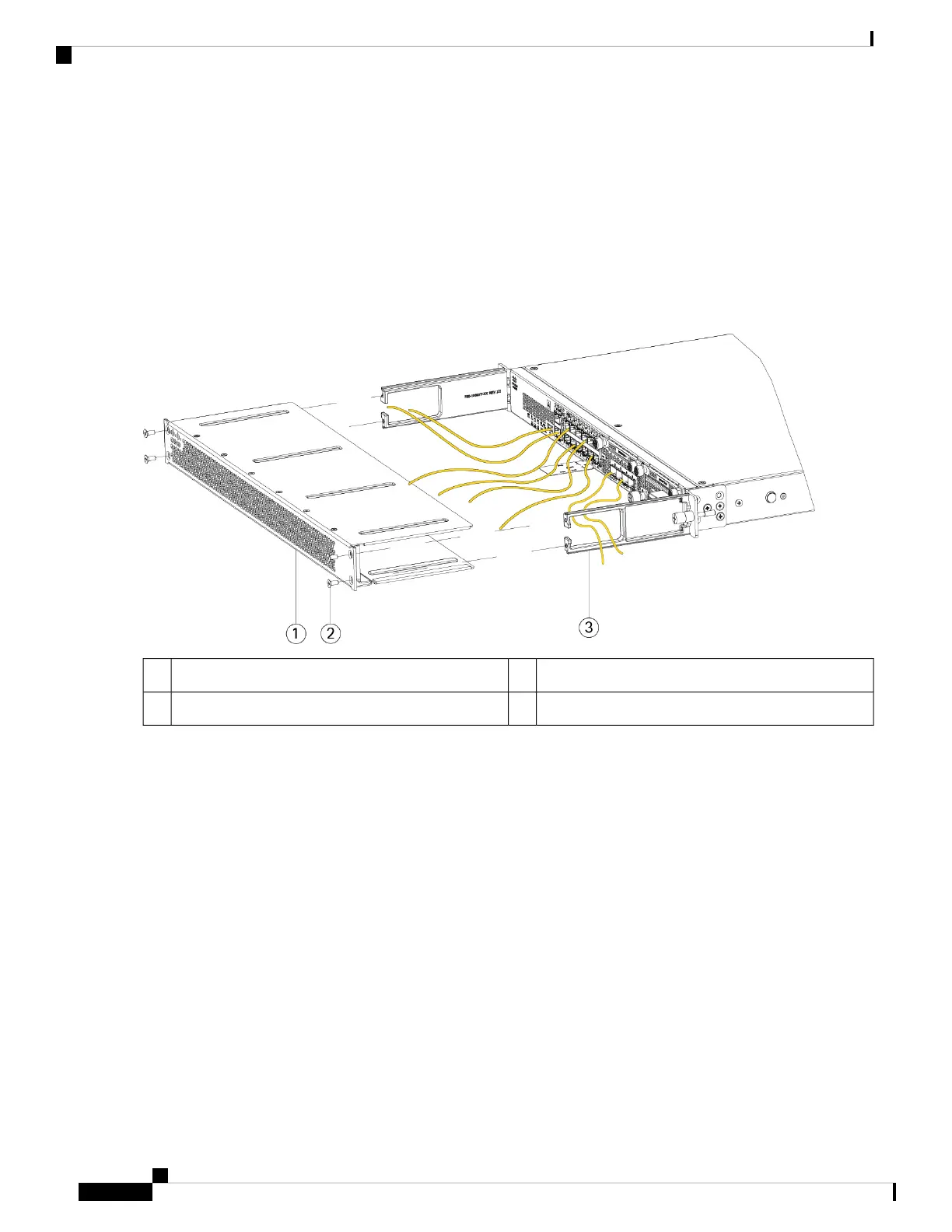
Step 4 Route the cables through the openings in the cable management brackets (see figure below).
Step 5 Attach the FIPS opacity shield to the cable management brackets using the four 8-32 x 0.375 inch Phillips screws
provided in the FIPS kit.
Figure 59: Route the Cables and Attach the Screws
8-32 x 0.375 inch-Phillips screws (two per side)2FIPS opacity shield1
Cable management bracket3
Step 6 Before you attach the TELs, clean the chassis of any grease, dirt, or oil with alcohol-based cleaning pads.
Step 7 Attach the seven TELs. See the figure below for the correct placement. Allow the TELs to cure for a minimum of 12
hours.
Any deviation in the placement of the TELs means the chassis is not in FIPS mode.
Caution
Cisco Firepower 2100 Series Hardware Installation Guide
86
Installation, Maintenance, and Upgrade
Install the FIPS Opacity Shield in a Four-Post Rack

 Loading...


