EasyManuals Logo

Cisco Firepower 2140 Hardware Installation Guide

Cisco Firepower 2140
84 pages
To Next Page IconTo Next Page
To Previous Page IconTo Previous Page
Page #78 background imageLoading...
Page #78 background image
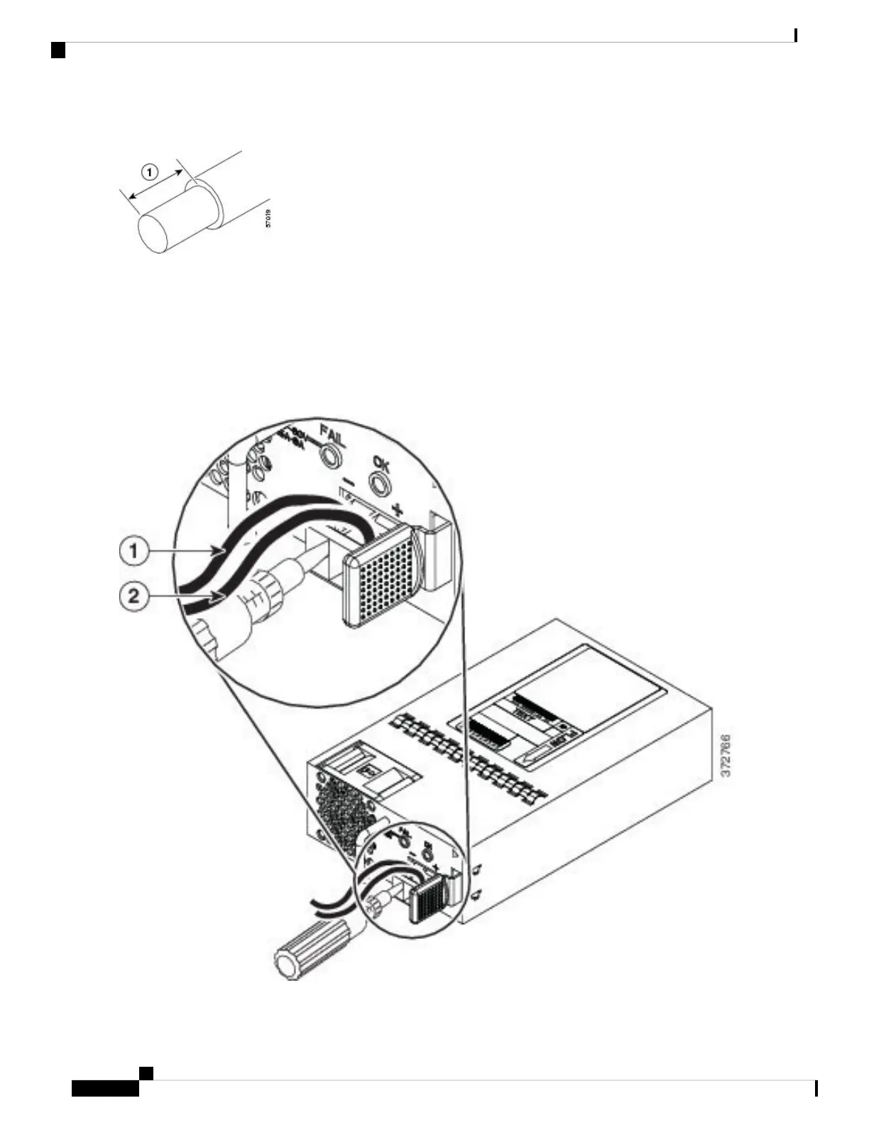
Figure 50: Stripped DC Input Source Wire
Step 4 Insert the exposed wire into the terminal block. Ensure that you cannot see any wire lead outside the plastic cover. Only
wires with insulation should extend from the terminal block.
Step 5 Use a screwdriver to tighten the terminal block captive screws.
Do not overtorque the terminal block captive screws. Make sure that the connection is snug, but the wire is not
crushed. Verify by tugging lightly on each wire to make sure that they do not move.
Caution
Figure 51: Tighten the Terminal Block Captive Screws
Cisco Firepower 2100 Series Hardware Installation Guide
74
Maintenance and Upgrade
Connect the DC Power Supply Module

Other manuals for Cisco Firepower 2140

Questions and Answers:

Question and Answer IconNeed help?

Do you have a question about the Cisco Firepower 2140 and is the answer not in the manual?

Cisco Firepower 2140 Specifications

General IconGeneral
ModelCisco Firepower 2140
CategoryFirewall
Firewall Throughput20 Gbps
Power SupplyDual, Hot-swappable
Firewall Throughput (Maximum)20 Gbps
Firewall Throughput (Application Visibility and Control AVC)10 Gbps
Form Factor1 RU
Memory32 GB
Operating SystemCisco Firepower Threat Defense (FTD)
Maximum Concurrent Sessions4, 000, 000
Network Interfaces8 x 1G/10G SFP+
Concurrent Sessions4, 000, 000
Interfaces8 x 1G/10G SFP+
Throughput20 Gbps

Related product manuals