RF Assembly
Become familiar with the function and component layout of the RF assembly before
aligning the 1.2 GHz GS7000 Node. The cover of the RF assembly is printed with a
diagram that shows the functional signal flow and identifies each field-replaceable
component.
Some of these components (pads, equalizers, and node signal directors) are removed
and replaced with different value components during the setup procedures.
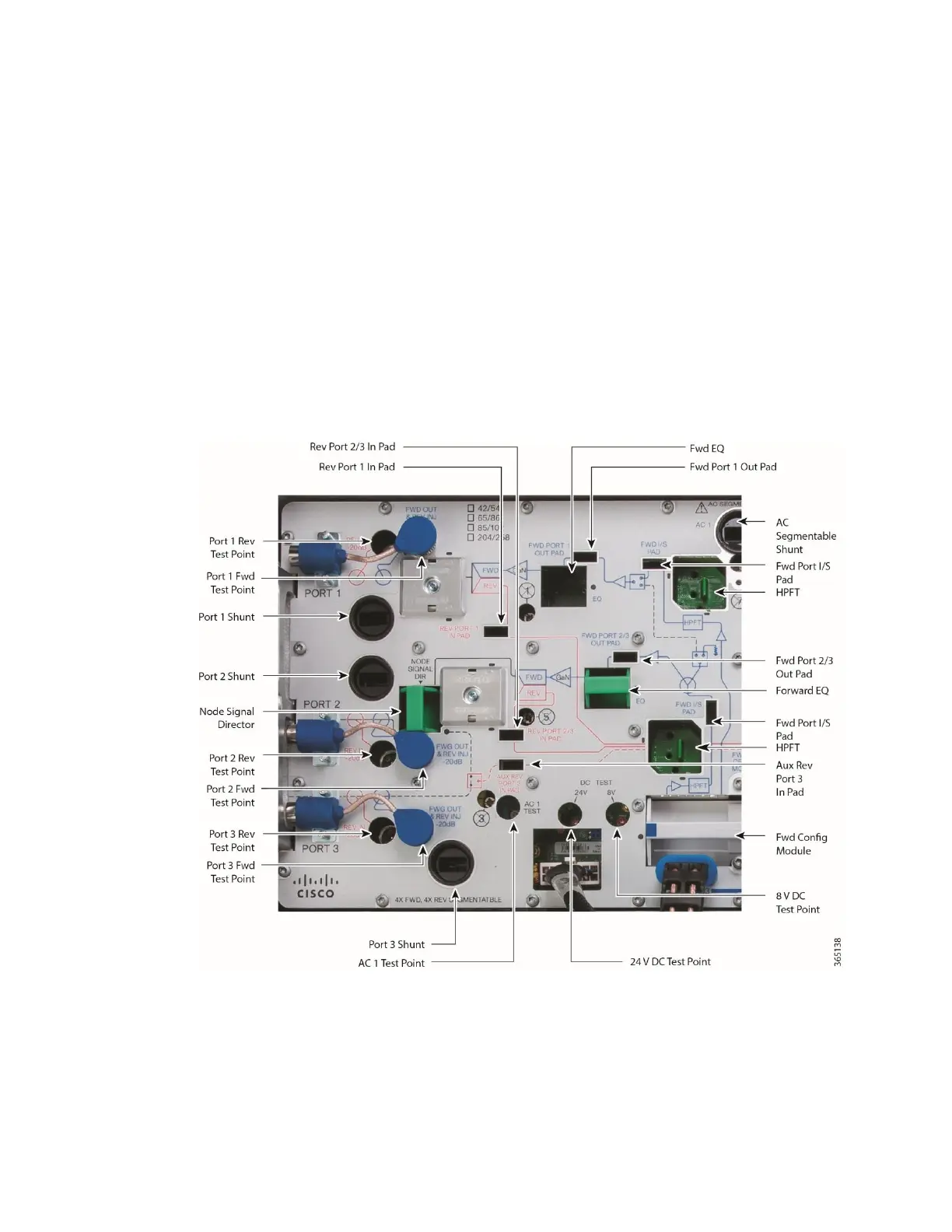
4-Way Forward Segmentable Node RF Assembly
The following illustrations show the 4-way forward segmentable node RF assembly.
Left side Ports 1, 2, and 3 illustration.