Removing and Replacing Modules
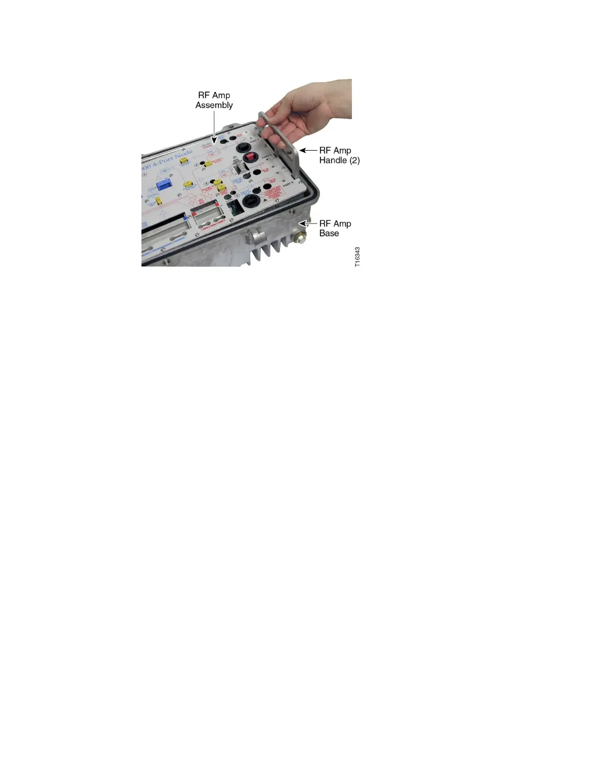
6 To replace the RF amplifier assembly in the housing, carefully align the assembly
in the housing, lower it into place and push down to reconnect the rear panel
connectors.
7 Secure the RF amplifier assembly to the housing with the seven cross-head
shoulder screws.
Important: Tighten the screws in order by number, 1 through 7. Repeat the
sequence twice, ending with a torque of 18 to 20 in-lbs (2.0 to 2.25 Nm).
8 Reinstall the AC power shunts in their proper locations on the RF amp assembly.
9 Close the housing. See Opening and Closing the Housing (on page 122).
10 Perform the setup procedure in Chapter 4 to verify node performance.