redundancy when no status monitor is present
Fiber entry ports on both ends of housing lid
Fiber management tray and track provides easy access to fiber connections
Primary and redundant power supplies with passive load sharing
Spring loaded seizure assemblies allow coax connectors to be installed or
removed without removing amplifier chassis or spring loaded mechanism
from the rear of the housing base
Dual/Split AC powering
Space provided for mounting WDM modules inside the housing lid.
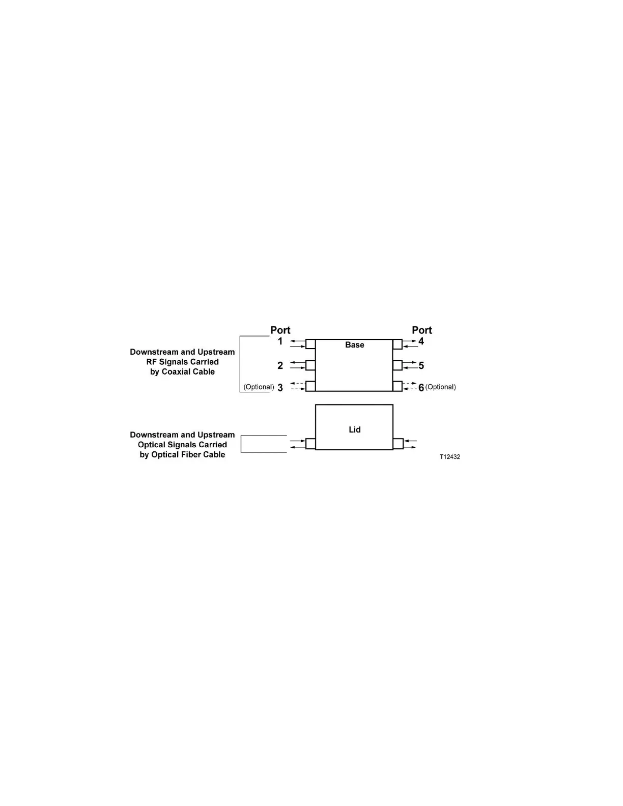
Node Inputs/Outputs Diagram
The following diagram shows the system-level inputs and outputs of the 1.2 GHz
GS7000 Node.
The AC can be applied to any RF port and routed, if required, to the other
ports.
The DC power supply modules can be fed by any RF port (1 through 6).
Modules Functional Descriptions
This table briefly describes each module. The 1.2 GHz GS7000 Node may not contain
all these modules. See Theory of Operation (on page 15) for detailed descriptions of
the modules.