Cisco IE 3000 Switch Getting Started Guide
20
Cisco IE 3000 Switch Getting Started Guide
OL-16234-01
Attaching the Power and Relay Connector
Follow these steps to connect the DC power and relay connector to the switch:
Caution The input voltage source of the alarm circuits must be an isolated source and
limited to less than or equal to 30 VDC, 1 A.
Step 7
Connect the other end of the positive wire (the one connected to V) to the positive terminal
on the DC power source, and connect the other end of the return wire (the one connected to
RT) to the return terminal on the DC power source.
Step 8
When you are testing the switch, one power connection is sufficient. If you are installing the
switch and are using a second power source, repeat Step 3 through Step 7 using a second
power and relay connector.
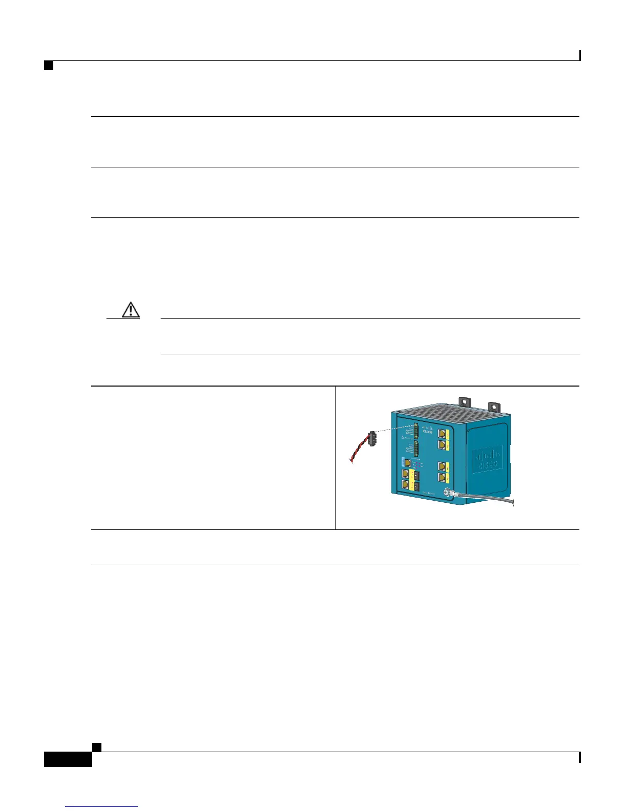
Step 1
Insert the power and relay connector into the
Pwr A receptacle on the switch front panel.
Step 2
Use a flathead screwdriver to tighten the captive screws on the sides of the power and relay
connector.
VRTA A
202332
 Loading...


