7
Getting Started and Product Document of Compliance for the Cisco IR1101 Industrial Integrated Services Router
Connecting to the Router Gateway Ports
For hazardous location environments, follow these warnings when connecting to the destination ports (antenna, serial,
Ethernet, and console ports).
Warning: If you connect or disconnect the console cable with power applied to the switch or any device on the
network, an electrical arc can occur. This could cause an explosion in hazardous location installations. Be sure that
power is removed or the area is nonhazardous before proceeding. Statement 1080
Warning: Do not connect or disconnect cables to the ports while power is applied to the switch or any device on
the network because an electrical arc can occur. This could cause an explosion in hazardous location installations.
Be sure that power is removed from the switch and cannot be accidentally be turned on, or verify that the area is
nonhazardous before proceeding. Statement 1070
Connecting to the USB Port
NOTE: If you are connecting to the USB port:
- a connection (to the USB port) can only be made in a non-hazardous environment
- the USB port cover must be reinstalled before the router can be deployed in a hazardous environment
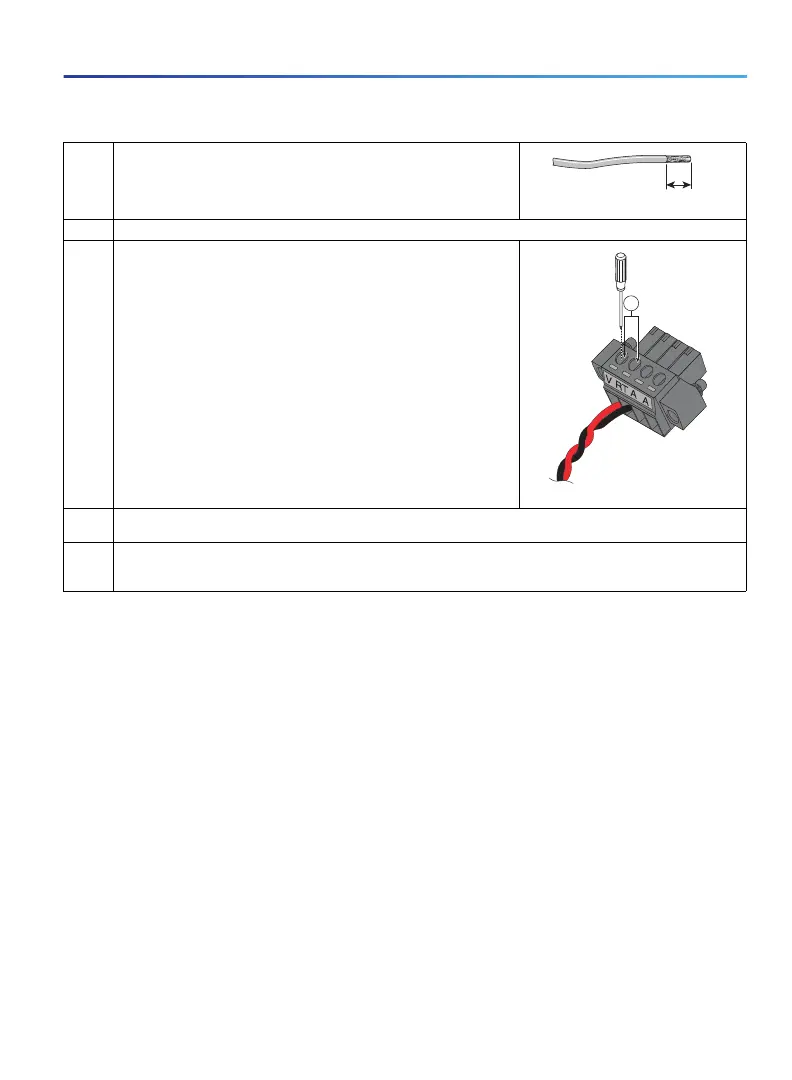
4. Using an 18-gauge wire-stripping tool, strip each of the two twisted pair
wires coming from each DC-input power source to 0.25 inch (6.3 mm)
± 0.02 inch (0.5 mm). Do not strip more than 0.27 inch (6.8 mm) of
insulation from the wire. Stripping more than the recommended amount of
wire can leave exposed wire from the power connector after installation.
5. Remove the two captive screws that attach the power and alarm connector to the router, and remove the connector.
6. On the power and alarm connector, insert the exposed part of the positive
wire into the connection labeled "V" and the exposed part of the return
wire into the connection labeled "RT". Make sure that you cannot see any
wire lead. Only wire with insulation should extend from the connector.
NOTE: Use the same method for wiring the alarm connections.
1—Power connector captive screws
7. Use a ratcheting torque flathead screwdriver to torque the power connector captive screws (above the installed wire
leads) to 2 in-lb (0.23 N-m).
8. Connect the other end of the positive wire to the positive terminal on the DC power source, and connect the other
end of the return wire to the return terminal on the DC power source.
Connect the other end of the Alarm wires to your alarm source.
333084
391942
1
 Loading...