1-26
Cisco Nexus 5000 Series Hardware Installation Guide
Chapter 1 Overview
Cisco Nexus 5500 Platform Switches
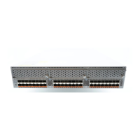
Figure 1-26 Cisco Nexus 5548 Fan Module
The bicolor fan module LED indicates the fan tray health. Green indicates normal operation, while
amber indicates a fan failure. For more information on this LED, see Table D-1 on page D-2. The Cisco
Nexus 5548UP has front-to-back (port-side exhaust) or back-to-front (port-side intake) airflow. The
Cisco Nexus 5548P has front-to-back (port-side exhaust) airflow only.
Caution All of the power supply and fan modules in the same chassis must use the same airflow direction or an
error will occur with possible over heating and shut down of the switch. If you power up the switch with
more than one airflow direction, you must power down the switch and replace the modules with the
wrong airflow direction (modules not taking in coolant air from the cold aisle) before powering up the
switch.
Transceivers and Cables
The Cisco Nexus 5548UP switch supports 10-Gigabit Ethernet and FCoE SFP+ and FET transceivers,
and the Cisco Nexus 5548P switch supports 10-Gigabit Ethernet SFP+ and FET transceivers. The
expansion modules support 1- and 10-Gigabit Ethernet SFP+ transceivers (N55 M16P expansion
module), 10-Gigabit FET transceivers, and Fiber Channel SFP transceivers.
This section includes the following topics:
• Transceivers, page 1-26
• Cables, page 1-28
Transceivers
Table 1-3 lists the supported transceiver options.
239113
1
2
3
1 Handle 3 Captive screw
2 Bicolor LED (green or amber)