1-49
Cisco Nexus 5000 Series Hardware Installation Guide
Chapter 1 Overview
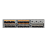
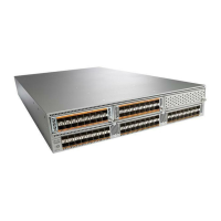
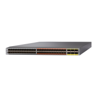
Cisco Nexus 5000 Platform Switches
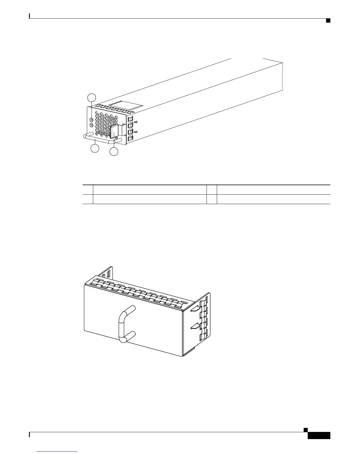
Figure 1-55 Power Supply for the Cisco Nexus 5010 Switch
For information on the LEDs see Table D-1 on page D-2. To see what combinations of these LEDs
indicate, see Table D-2 on page D-3.
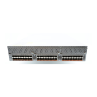
If you have one power supply installed in the chassis, but the other power supply slot is empty, you
should use a blank panel to cover the empty slot. Figure 1-56 shows a blank power supply panel.
Figure 1-56 Blank Power Supply Panel
Fan Modules
The Cisco Nexus 5010 switch has slots for two fans modules. Each fan module houses six fans and each
uses front-to-back (port-side exhaust) airflow. If you insert 2 fan modules (with 6 fans in each module),
your switch will have a total of 12 fans. Figure 1-26 shows the fan module.
1 FAIL (top) and OK (bottom) LEDs 3 Release latch
2 Handle
186854