Screw holes (6) for
attaching a mounting
bracket
5Lane link status LEDs for
4x10-Gigabit port
configuration (1 LED lit
to show the lane being
checked or all LEDs off
when all 4 lanes are being
checked)
2
Grounding pad6Lane shift button3
To determine which transceivers, adapters, and cables are supported by this switch, see the Cisco Transceiver
Modules Compatibility Information document.
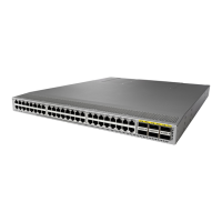
The following figure shows the switch features on the power supply side of the chassis.
Console port (1)6Power supply modules (1
or 2) (AC power supplies
shown) with slots
numbered 1 (left) and 2
(right)
1
USB port (1)7Fan modules (4) with slots
numbered from 1 (left) to
4 (right)
2
Management port (RJ-45)8L1 port (software defined)3
Screw holes (6) for
attaching a mounting
bracket
9L2 port (software defined)4
Grounding pad10Beacon (BCN) and Status
(STS) LEDs
5
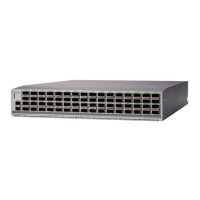
Depending on whether you plan to position the ports in a hot or cold aisle, you can order the fan and power
supply modules with port-side intake or port-side exhaust airflow. For port-side intake airflow, the fan and
AC power supply modules have burgundy coloring (DC power supply modules have green coloring). For
port-side exhaust airflow, the fan and AC power supplies have blue coloring (DC power supply modules have
gray coloring). You can also order the 1200-W HVAC/HVDC power supply which has dual-direction airflow
Cisco Nexus 9236C NX-OS Mode Switch Hardware Installation Guide
3
Overview
Overview
 Loading...