Do you have a question about the Cisco Nexus 9336C-FX2 and is the answer not in the manual?
This publication is for hardware installers and network administrators who install, configure, and maintain Cisco Nexus switches.
Command descriptions use the following conventions.
To provide technical feedback on this document, or to report an error or omission, please send your comments.
The switch requires an operating temperature of 32 to 104 degrees Fahrenheit (0 to 40 degrees Celsius).
Electromagnetic interference (EMI) and radio frequency interference (RFI) from the switch can adversely affect other devices.
The switch is sensitive to variations in voltage supplied by the power sources. Overvoltage, undervoltage, and transients (or spikes) can erase data from memory or cause components to fail.
You can install the following types of racks or cabinets for your switch.
Before you install, operate, or service the switch, see the Regulatory, Compliance, and Safety Information.
When installing the switch, follow these guidelines.
Before you install the switch, be sure to unpack and inspect the switch for damage or missing components.
To install the switch, you must attach front and rear mounting brackets to the switch, install slider rails on the rear of the rack.
Before you create a network management connection for the switch or connect the switch to the network, you must create a local management connection through a console terminal.
You must assign an IP address to the switch management interface so that you can then connect the switch to the network.
You can replace a fan module while the switch is operating so long as you perform the replacement within one minute.
The switch requires two power supplies for redundancy. You can replace the other power supply during operations.
The cabinet or rack must also meet the following requirements.
A perforated cabinet has perforations in its front and rear doors and side walls. Perforated cabinets must meet the following requirements.
The following table lists the environmental specifications for the switch.
The following table lists the typical amount of power consumed by the switch, and it lists the maximum amount of power that you must provision from the power source.
Power specifications include the specifications for each type of power supply module.
The BCN, STS, and ENV, LEDs are located on the left side of the front of the switch.
The fan module LED is located below the air holes on the front of the module.
The power supply LEDs are located on the left front portion of the power supply.
The following table lists and illustrates the contents for the 1RU rack-mount kit (NXK-ACC-KIT-1RU).
Planning the location and layout of your equipment rack or cabinet is essential for successful switch operation, ventilation, and accessibility.
Use the following worksheet to record information about the switch.
| Switching Capacity | 7.2 Tbps |
|---|---|
| Forwarding Rate | 5.4 bpps |
| Rack Units | 1 RU |
| Form Factor | Rack-mountable |
| Jumbo Frame Support | Yes |
| Jumbo Frame Size | 9216 bytes |
| Operating System | Cisco NX-OS |
| Memory | 16 GB |
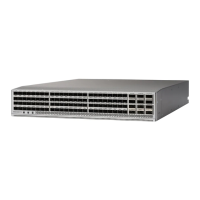
| Ports | 36 fixed 40/100 Gigabit Ethernet QSFP28 ports |
| Power Supply | Dual redundant power supplies |
| Airflow | Port-side exhaust or port-side intake |
| Product Type | Switch |
| Dimensions | 1.72 x 17.3 x 22.5 in (4.37 x 43.94 x 57.15 cm) |
| Flash Memory | 64 GB |
| Latency | Sub-microsecond |