Do you have a question about the Cisco Nexus 93108TC-FX and is the answer not in the manual?
Defines the intended audience for this hardware installation guide.
Explains the typographical conventions used in command descriptions and the document.
Lists other Cisco documentation relevant to the ACI fabric and Nexus switches.
Provides contact information for submitting technical feedback or reporting errors.
Details how to find Cisco documentation and submit service requests.
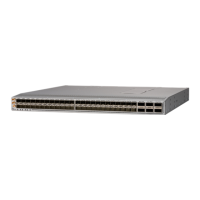
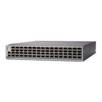
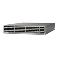
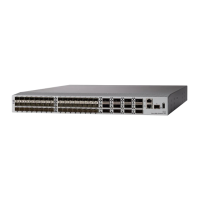
Provides a high-level description of the Cisco Nexus 93108TC-FX switch and its components.
Specifies the operating and non-operating temperature ranges for the switch.
Details the acceptable relative humidity levels for the switch to prevent moisture damage.
Lists the maximum altitude for switch operation and potential issues at higher altitudes.
Explains the impact of dust and particles on switch performance and how to avoid contamination.
Provides guidelines to reduce EMI and RFI affecting or emitted by the switch.
States that the switch has been tested for shock and vibration resistance.
Details the importance of proper grounding for switch protection and operational stability.
Covers switch power supply types, redundancy, and circuit requirements.
Explains airflow directions (intake/exhaust) for cooling and their importance for switch operation.
Specifies the types of racks and cabinets suitable for installing the switch.
Details the necessary physical space around the chassis for airflow, cabling, and maintenance.
Provides essential safety warnings and instructions before installing or operating the switch.
Covers rack installation types, airflow considerations, and general installation best practices.
Guides on how to unpack the switch and check for any damage or missing components.
Step-by-step instructions for physically mounting the switch in a rack using mounting brackets.
Details the procedures for properly grounding the switch chassis for safety and stability.
Instructions for connecting power and initiating the switch startup sequence.
Describes the main components and connections within the Cisco ACI fabric.
Considerations for interface types, cabling, and equipment needed for connections.
Explains how to connect leaf switches to Application Policy Infrastructure Controllers (APICs).
Details the process of connecting leaf switches to spine switches for fabric connectivity.
Guides for establishing console and out-of-band management connections for the switch.
Provides best practices for cleaning and maintaining optical transceivers and cables.
Lists types of cabinets and racks suitable for switch installation.
Specifies general requirements that cabinets and racks must meet.
Details specific requirements for mounting the switch in open racks.
Outlines specific requirements for perforated cabinets, focusing on airflow.
Offers advice on managing cables within the rack for better organization and airflow.
Lists environmental operating conditions such as temperature, humidity, and altitude.
Provides physical dimensions, weights, and quantities for the switch and its modules.
Details the typical and maximum power consumption of the switch.
Specifies electrical characteristics for 500W AC, 1200W HVAC/HVDC, and 930W DC power supplies.
Lists power cord part numbers and descriptions for AC, HVAC/HVDC, and DC power supplies.
Lists the safety and EMC standards the product complies with.
Describes the BCN, STS, and ENV LEDs on the front of the switch chassis.
Explains the status (STS) LED on the fan modules.
Details the status indications provided by the power supply LEDs.
Lists the components included in the standard accessory kit for the switch.
A checklist of tasks to complete before installing the switch for optimal operation.
Worksheet to record essential contact and site details for the installation.
Worksheet to record serial numbers, IP addresses, and module details of the switch.
| Model | Nexus 93108TC-FX |
|---|---|
| Product Type | Switch |
| Manufacturer | Cisco |
| Power Supply | Dual redundant power supplies |
| Operating System | Cisco NX-OS |
| Memory | 16 GB |
| MAC Address Table Size | 128, 000 entries |
| Jumbo Frame Support | Up to 9216 bytes |
| VLANs | 4096 |
| Humidity | 5% to 95% non-condensing |
| Throughput | 1.2 Bpps |
| Latency | 1 microsecond |
| Routing Protocol | BGP, OSPF, EIGRP, RIP, IS-IS |
| Features | VXLAN |
| Compliant Standards | IEEE 802.1Q |
| AC Power Input | 100-240 VAC |
| Operating Temperature | 0 to 40 °C |
| Storage Temperature | -40°F to 158°F (-40°C to 70°C) |
| Form Factor | 1U |
| Ports | 48 x 10/100/1000 Ethernet, 6 x 40/100 Gigabit Ethernet QSFP28 |