Do you have a question about the Cisco Nexus 9508 NX-OS and is the answer not in the manual?
Defines the intended audience for this hardware installation guide.
Explains the typographical and syntax conventions used throughout the document.
Lists other relevant Cisco documentation for the NX-OS software.
Provides contact information for submitting feedback or reporting errors in the document.
Information on how to get more documentation and submit service requests.
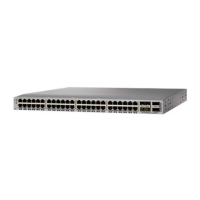
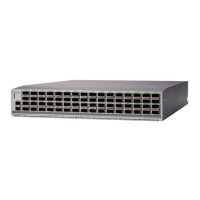
Introduces the switch chassis, its components, and slot assignments.
Specifies the required operating and non-operating temperature ranges for the switch.
Details acceptable humidity levels for switch operation and maintenance.
Outlines altitude considerations for switch installation based on power supply.
Advises on environmental cleanliness to prevent contamination and damage.
Provides guidelines to reduce EMI/RFI interference for reliable operation.
States that the switch has been tested for shock and vibration resistance.
Explains the importance and methods for grounding the switch for safety.
Guides users on calculating and planning for the switch's power needs.
Specifies physical requirements for racks and cabinets to house the switch.
Details necessary space around the chassis for airflow and servicing.
Instructions for preparing and securing a rack or cabinet for the switch installation.
Steps for unpacking and verifying the contents and condition of the new switch.
Procedure for attaching bottom-support rails to the rack for chassis stability.
Detailed steps for physically mounting the switch chassis into a rack.
Instructions for connecting the chassis to the data center ground for safety.
Steps to ensure prerequisites are met before powering on the switch.
Best practices for connecting transceivers and cables to the switch ports.
How to establish a local management connection using a console terminal.
Steps to connect the switch's management port for network access.
Guide to the initial setup process, including IP address configuration.
General guidance on connecting network interface ports using various transceivers.
Specific instructions for connecting copper network cables.
Procedure for removing copper network cables.
Instructions for connecting fiber-optic network cables using transceivers.
Procedure for removing fiber-optic cables and transceivers.
Detailed steps for safely removing optical transceivers with a tool.
Guidelines for cleaning and maintaining optical components for optimal performance.
How to display information about installed hardware using 'show hardware'.
Retrieving FRU information like product IDs and serial numbers.
Accessing backplane SPROM data, including serial numbers.
Monitoring switch environmental status, including power supply and module temperatures.
Checking the operational status and conditions of installed modules.
Viewing temperature readings for various sensors within modules.
Establishing direct CLI access to specific modules for management.
Procedures for saving module configurations to nonvolatile storage.
Commands to power off or power on specific modules within the chassis.
Clearing configuration for non-functional modules to reset them.
Viewing the power consumption of all modules and the switch.
Resetting a specific module without rebooting the entire switch.
Procedures for restarting the entire network switch.
Information on the types and functions of supervisor modules.
Explanation of different power redundancy modes and their configurations.
Essential safety precautions to avoid ESD damage when handling components.
Step-by-step guide for installing or replacing supervisor modules.
Instructions for installing or replacing system controller modules.
Detailed procedure for installing or replacing line cards.
How to install and remove blank line cards to fill empty slots.
Steps for removing and replacing fan trays for cooling system maintenance.
Procedure for replacing fabric modules, essential for switch connectivity.
Guide to installing or replacing power supply units for continuous operation.
Steps for upgrading line cards to newer, higher-speed models.
Lists environmental operating parameters like temperature, humidity, and altitude.
Provides physical dimensions of the chassis and its modules.
Lists the weight of various chassis components for handling and installation.
Details power requirements and maximum available power for the switch.
Explains the status indicators on the main chassis.
Describes the LEDs on the system controller modules.
Explains the LEDs on the supervisor modules for status indication.
Describes the LED indicators on the fan trays.
Explains the LEDs on the fabric modules for status.
Describes the LEDs on the line cards indicating port and module status.
Explains the LED indicators on the power supply modules.
Lists the contents of the accessory kit for installation and mounting.