Do you have a question about the Cisco Nexus 9348GC-FXP NX-OS and is the answer not in the manual?
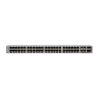
The Cisco Nexus 9348GC-FXP switch (N9K-C9348GC-FXP) is a 1-RU fixed-port, L2/L3 switch, designed for deployment in data centers.
The switch is sensitive to variations in voltage supplied by the power sources. Overvoltage, undervoltage, and transients (or spikes) can erase data from memory or cause components to fail.
The switch includes two power supplies (1-to-1 redundancy with current sharing) in one of the following combinations: Two 350-W AC power supplies.
Before you install, operate, or service the switch, see the Regulatory, Compliance, and Safety Information for the Cisco Nexus 3000 and 9000 Series for important Safety Information.
To install the switch, you must attach front and rear mounting brackets to the switch, install slider rails on the rear of the rack, slide the switch onto the slider rails, and secure the switch to the front of the rack.
To install the switch, you must attach mounting brackets to the switch and secure the switch to the rack. Installation in racks other than 19-inch racks requires a bracket kit not included with the switch.
The switch chassis is automatically grounded when you properly install the switch in a grounded rack with metal-to-metal connections between the switch and rack.
You start the switch by connecting it to its dedicated power source. If you need n+1 redundancy, you must connect each of the power supplies to one or two power sources.
You need to connect the following ports when connecting the switch to the network: Console port, Management ports, Uplink and downlink ports.
You can connect the switch to a console to perform the following functions: Configuring the switch using the CLI, Monitoring network statistics and errors.
To prevent an IP address conflict, you must complete the initial configuration and establish an IP address for the switch.
After you perform the initial configuration for the switch and create a management connection, you are ready to connect the interface ports on the switch to other devices.
The QSFP+ transceiver module can have either a bail-clasp latch or a pull-tab latch.
You can replace one of the three fan modules at a time while the switch is operating so long as you perform the replacement within one minute.
You can replace a power supply with another supported power supply that has the same power source type (AC) and the same wattage rating as the other installed power supply.
Lists the typical and maximum power consumed by the switch and required input from the power source for peak conditions.
| Product Model | Nexus 9348GC-FXP |
|---|---|
| Switch Type | Fixed |
| Form Factor | 1 RU |
| Jumbo Frame Support | Yes |
| Jumbo Frame Size | 9216 bytes |
| Operating System | Cisco NX-OS |
| Memory | 16 GB |
| Flash Memory | 16 GB |
| VLANs | 4096 |
| Operating Temperature | 32 to 104°F (0 to 40°C) |
| Storage Temperature | -40 to 158°F (-40 to 70°C) |
| Humidity | 5 to 95% noncondensing |
| Layer Support | Layer 2, Layer 3 |
| Power Supply | Dual hot-swappable power supplies |
| Buffer Size | 12 MB |
| Input Voltage | 100-240 VAC |
| Dimensions (H x W x D) | 1.72 x 17.3 x 18.1 in (4.4 x 43.9 x 46.0 cm) |
| DC Power Input | -40 to -72 VDC |
| Ports | 48 x 1/10/25-Gbps and 4 x 40/100-Gbps |