Use colored cables to designate positive and negative polarity. You need two cables that are colored for positive
polarity and two cables that are colored for negative polarity.
b) Use a crimping tool to attach each of four lugs (provided with the switch for each power supply) to the stripped end
of each cable.
Test each crimped lug by trying to pull it off its cable.
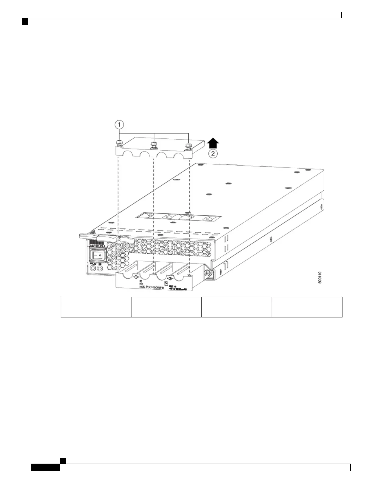
c) Use a torque screwdriver to unscrew the three screws that are on the cover of the terminal box. the cover is located
on the front of the power supply and lifts off the cover as shown in the following figure.
Remove the cover.2Unscrew three screws on
the safety cover.
1
The terminal box has four slots for four power terminals (ordered as negative [-], positive [+], positive [+],
and negative [-]). Each terminal has two nuts that you use to fasten a power cable to the terminal.
Note
d) Remove the two nuts from each terminal post in each slot of the terminal box.
e) Place each of the lugs for the two positive cables on the two middle terminal posts and fasten each lug using two
nuts. Then tightened to 40 in-lb (4.5 N·m) of torque.
f) Place each of the lugs for the two negative cables on the two side terminal posts and fasten each lug with two nuts.
Then tightened to 40 in-lb (4.5 N·m) of torque.
g) Replace the safety cover on the terminal box and fasten it in place using its three screws.
h) Connect the other ends of the power cables to the two DC power circuits.
Be sure that the positive and negative cables that are attached to one side of the power supply are attached to the same
DC power source circuit. The negative cable is attached to a negative terminal and the positive cable is attached to
a positive terminal).
Cisco Nexus 9508 NX-OS Mode Switch Hardware Installation Guide
36
Installing a Chassis
Connecting a 3-kW DC Power Supply to a DC Power Source
 Loading...