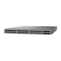
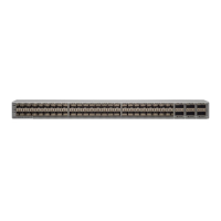
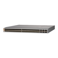
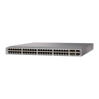
• If the switch has port-side exhaust modules (fan modules with blue coloring), position the switch so that its fan
and power supply modules will be in the cold aisle.
b) Position the front rack-mount bracket and the rear rack-mount bracket so that its screw holes are aligned to the screw
holes on the side of the chassis.
You can align the holes in the rack-mount bracket to the holes on the side of the chassis (see the two
ways to mount these brackets on a typical chassis, in following figure). The holes that you use depend
on the requirements of your rack and the amount of clearance required for interface cables (3 inches [7.6
mm] minimum) and module handles (1 inch [2.5 mm] minimum).
Note
c) Secure the front-mount bracket to the chassis using four M4 screws and tighten each screw to 12 in-lb (1.36 N·m)
of torque.
d) Repeat Step 1 for the other front rack-mount bracket on the other side of the switch and be sure to position that bracket
the same distance from the front of the switch.
Step 2 If you are not installing the chassis into a grounded rack, you must attach a customer-supplied grounding wire to the
chassis as explained in the Grounding the Chassis, on page 24 section. If you are installing the chassis into a grounded
rack, you can skip this step.
Step 3 Insert the switch into the rack and attach it as follows:
a) Holding the switch with both hands, position the brackets on the switch between the cabinet posts (see the following
figure).
Cisco Nexus 93108TC-FX3P ACI-Mode Switch Hardware Installation Guide
21
Installing the Switch Chassis
Installing the Switch into a Two-Post Rack Using the NXK-ACC-KIT-1RU Rack-Mount Kit

 Loading...


