All fan modules and power supplies must use the same airflow direction.
Note
In the event that only one power supply is operating in an active system and a
second power supply is inserted, the system fan will slow down to 50% of Max
speed for 12 seconds. It can take up to 10 seconds for the second power supply
to become active. Please do not remove the first power supply during this
time-frame, in order to avoid system shutdown.
Note
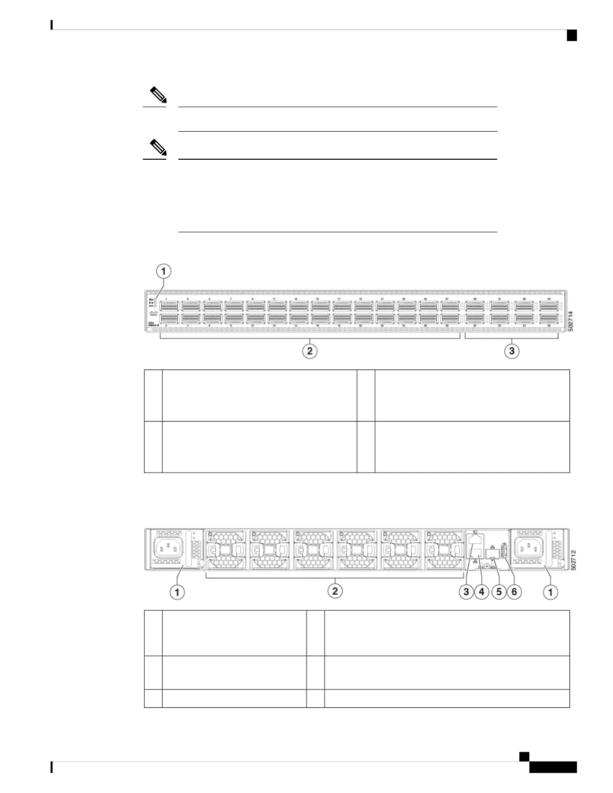
The following figure shows the switch features on the port side of the chassis.
8 100/400-Gigabit QSFP-DD ports
Ports 29-36 support 4x10 and 4x25G as port
profile converted downlinks
3Beacon (BCN), Status (STS), and Environment
(ENV) LEDs
1
28 40/100-Gigabit QSFP28 ports
Ports 25-28 support 4x10G and 4x25G breakout
as native downlinks
2
To determine which transceivers, adapters, and cables support this switch, see the Cisco Transceiver Modules
Compatibility Information document.
The following figure shows the switch features on the power supply side of the chassis.
Management port (1—RJ-45 copper port)4Power supply modules (1 or 2) (AC
power supplies shown) with slots
numbered 1 (left) and 2 (right)
1
Management port (1—SFP optical port)5Fan modules (6) with slots
numbered from 1 (left) to 6 (right)
2
USB port (1)6Console port (1)3
Cisco Nexus 93600CD-GX ACI-Mode Switch Hardware Installation Guide
3
Overview
Overview

 Loading...


